Although the subject item is often referred to in the singular, the Common Berthing Mechanism (CBM) actually operates as a single mechanism only in the process of being mated or demated. It has two distinct major assemblies: the Active Common Berthing Mechanism (ACBM) and the Passive Common Berthing Mechanism (PCBM). In general, these two sides are launched separately, being bolted to the Pressurized Element of which they are a part. There have, however, been a few special cases where an ACBM and PCBM are launched in the mated condition using the ACBM as if it were Flight Support Equipment1.
The CBM has six conceptual phases of action:
(1) Pre-berth prepares both sides and moves the PCBM into near proximity of the ACBM
(2) Capture transitions local control authority over the PCBM-equipped chase vehicle to the ACBM
(3) Rigidization establishes a competent primary structural joint across the interface plane
(4) De-rigidization relinquishes the primary structural joint across the interface plane
(5) Release relinquishes control authority over the departing vehicle
(6) Post-deberth dispositions both sides for subsequent operations
The first three phases are collectively referred to as “berthing”. The last three are typically called “deberthing”.
In addition to the active phases, the mated CBMs constitute a pressurized, inter-element compartment. The compartment is usually referred to as the “vestibule”. While pressurization of the vestibule influences the CBM, it is not considered to be a phase of CBM operation2.
Although the two “sides” were developed as a single project, they are distinct in concept:
– The ACBM is always found on the target vehicle, where electrical power is present. It may be either axially located and oriented, or radially located and oriented. All actively controlled mechanisms are found on the ACBM.
– The PCBM is always axially located and oriented on the chase vehicle, which might (or might not) have electrical power available in the pre-berth circumstance. There are several passive, spring-loaded mechanisms on the PCBM, but no actuated mechanisms. The PCBM may be either mounted on a flanged axial bulkhead3, or mounted on an axially-oriented circular flange4.
Each side (ACBM and PCBM) is built up on a Primary Structural ring holding the various components. The length of the ACBM ring is dominated by the fit of radially-mounted ACBMs in the dynamic envelope of the NSTS Payload Bay, which has a nominal diameter of 15 ft. The PCBM ring, being axially located and oriented in all cases, is less constrained in length. The ring inner diameters, which are identical, accommodate the passage of larger cargo than any other berthing or docking mechanism: at least 50″ in diameter, with room left on the perimeter for utility cables and lines between the Pressurized Elements.
Both sides are quadrilaterally symmetric. Each quadrant contains a capture latch/fitting pair, four bolt/nut pairs, alignment structures, and ancillary components.
The conceptual design implements a staged alignment technique during approach and capture. Multiple layers of structural components gradually mesh to enforce alignment in the plane of the interface between the two sides. Each stage transitions the constraint to the next stage as the axial distance between the two sides decreases. The transition is gradual: multiple stages can interact, depending on rotations about the in-plane axes. The final stage of alignment has sufficient precision to carry shear loads across the vestibule. In all cases, the alignment structures preclude unintended contact between surfaces that are not designed it.
The various combinations of contact angle, contact stress, and friction during alignment are critical aspects of the design. The nominal contact surfaces are oriented tangentially with respect to the ring. Tangential contact mitigates the risk of forces acting in opposition across any chord of the ring face to reduce the risk of jamming and wedging during actuation of capture latches and bolts. As a practical matter, edge and corner radii make it impossible to perfectly eliminate that risk.
The dual-sided CBM/CBM “face” seal is located on the PCBM for ease in maintenance actions over repeated logistic berthing events. The face seal is a structural member bolted to the PCBM structural ring. Four actuated bolts are located in each quadrant of the ACBM, each bolt mating with a nut on the PCBM to compress the face seal and rigidize the joint. Large-diameter o-rings seal the factory joint where each ring is bolted to its respective element.
The conceptual design has only one nominal interface plane for on-orbit operations. The field joint seal, capture mechanisms, bolt mechanisms, and alignment structures are co-located at, or very close to that plane, relative to the magnitude of motion for any of the operational phases.
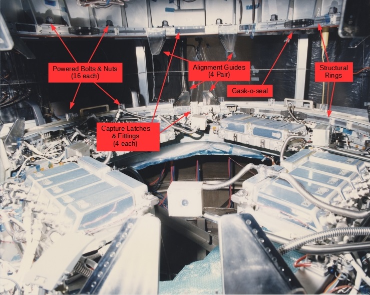
The CBM had more than one detailed configuration during its developmental period. At least three5 can be compared to illustrate the conceptual design’s continuity. Figure 16 shows the general arrangement of the design as it existed circa 1991. Figure 27 is a composite of the two Thermal Balance test articles about five years later. Figure 38 peers across the CBM/CBM interface plane during Qualification testing in early 1998. Details changed, and some features were added along the way, but the conceptual design features as they’re described above apply at all three points in time.

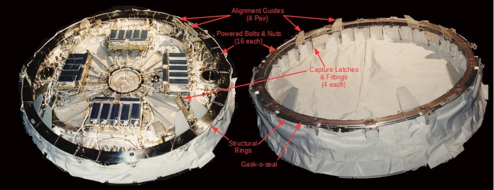 Figure 2: Thermal Balance configuration circa 1996 (ACBM on the left; Original photo credit: Boeing/NAS15-10000)
Footnotes
- PMA1, PMA2, and Cupola.[↩]
- That is, the functional requirements for letting air into the vestibule were not allocated to the CBM in the Development Specifications. See S683-29902B.[↩]
- Of an element that is pressurized before berthing[↩]
- Of an element is internally open to vacuum prior to berthing[↩]
- Hints at a fourth configuration can be seen in MDAC H3913 “Berthing Mechanism Final Test Report and Program Assessment (October 1988, NTRS record 19890009146). According to the report, an “advanced development” project began in 1985. The report contains forward references to Work Package 01 under what (eventually) became the International Space Station program. Other than a reference to the 50″ diameter opening, however, it is not clear from the report what specific technical details of the final design followed from that effort. Much of what can be seen in Figure 6-9 of the report appear to be qualitatively distinct from those of any CBM concept on record.[↩]
- Illi, Erik, “Space Station Freedom Common Berthing Mechanism”, The Boeing Company, Huntsville, AL (1992). Contract NAS8-50000.[↩]
- Original photo credit: Arnold Engineering Development Center, Tullahoma, TN. (MAR 1996)[↩]
- Original photo credit: The Boeing Company, Huntsville, AL (1998). Contract NAS15-10000.[↩]