A Functional Flow Block Diagram (FFBD) is a simple way to show the sequential relationships between a set of Functions. The original concept can be extended to make it more useful to later stages of Developmental Engineering, having little arcane symbology and requiring no proprietary software tools1. The extended FFBD imposes few (if any) constraints beyond the fundamentals.
The notion for describing a sequence of functions is to abstractly show how the functions control values for those parameters that characterize a system’s behavior. Here, the word “control” is used from the perspective of the Developer, at “design time”. All of the values will be controlled: some as explicit, observable features of the design that are implemented during manufacture, some as implicit features of the design that are not directly observable during manufacture, and some as the objective of real-time control algorithms.
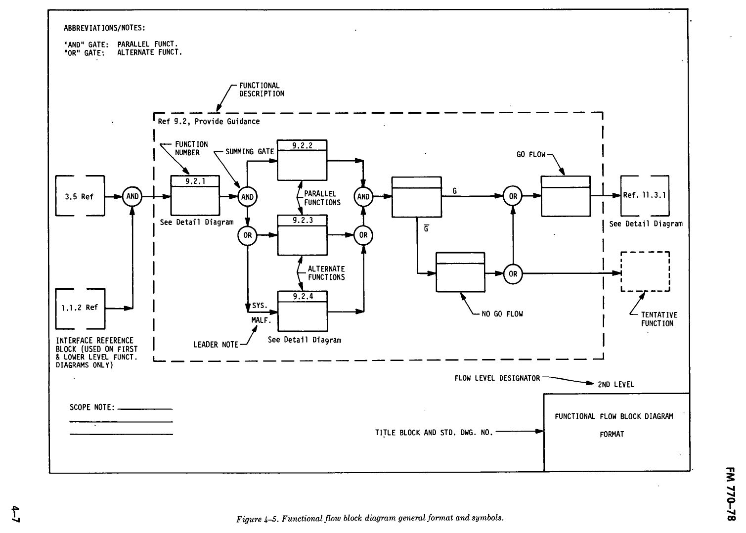
It is possible that the origin of the FFBD is lost in the mists of time. Although my first exposure was on a chalkboard during an OJT session, the earliest definitive reference of which I am aware is in section 4.2.a of the long-since cancelled FM770-78 (see Figure 1). I still use this document as a primary reference because I have found no replacement to provide a superior description of the philosophical concepts2.
Aside
FM770-78 imposes stringent formatting requirements with heavy emphasis on traceability. I find that emphasis obscures the technical utility of the concept, so I do not directly address it in this material. Any form of traceability is acceptable if it works in the prevailing bureaucratic context. In support of commonality, I usually don’t use the diagram itself to record “parentage” (upward traceability). My preference is maintain that data in a separate database, with the FFBD having no more than a globally unique identifier for each unique function as assigned by the database engine.
Function Blocks
A sample of acceptable approaches for showing individual functions and their associated parameters are shown in Figure 2.
– (a) is a trivial case, in which the values of three parameters admit to a function that changes all the values.
Aside
It is easy to interpret the parameters (and values) shown to the left and right of each function as “inputs” and “outputs”. That interpretation is incorrect, and can easily lead to misperception of the function itself. Although they might be inputs to a process inside the function, those on the right are better thought of as “values that admit to (and possibly force) the execution of the function”. Similarly, those on the left are better thought of as “values occurring as a consequence of the function’s execution”. When I’m paying close attention, I’ll refer to them as “admitting” and “consequential”, respectively3.
– (b) supports the notion that a function can originate the relevance of a parameters; subfigure (c) demonstrates a perfectly acceptable alternative (Parameter C being “null” or “empty” before execution of the function). It also suggests that “special symbols” are acceptable. Of course, they should be clearly defined somewhere that’s readily accessible to the reader.
– (d) suggests that values are actually ranges, and might have a relationship that is expressed internal to the function itself. The potential for an implicit relationship should raise suspicion. I’d probably ask many pointed questions about whether the ranges are externally driven rather than the result of an algorithm internal to the function. I would not (however) reject it out of hand.
– In sub-figure (d), parameter B disappears across the function. This implies it is a “circumstance” rather than a parameter who’s value is intentionally changed or maintained across the function. Pure circumstantial parameters typically don’t appear on an FFBD. They are, however, sometimes necessary to indicate which branch of an FFBD will be taken under what…circumstances4. An example of that situation is found here.
Aside
The general exclusion of “circumstances” from a synthesis FFBD means that it doesn’t necessarily contain enough information to directly support an executable model of the system’s behavior. An FFBD is intended as a structural model of the system in an ad-hoc “function space”, communicating little more than what will be evaluated to determine whether each function occurred. An emulating model5 would require addition of the circumstances and simplified representations of essential algorithms and relationships6. A simulating model7 would require knowledge of the cause-and-effect relationships inherent in a specific design8 (e.g., physics, algorithms).
– (e) addresses the possibility that a mere listing of parameters (and permissible values) may, in fact, be too extensive to appear directly on an FFBD at all. Concrete references, which might be as simple as an attached note, are acceptable.
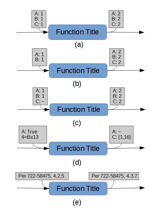
To summarize the basic intent, there is but one requirement for listing parameters (and values) that are associated with Functions: that the listing(s) be subject to exactly one interpretation. In this context, ambiguity is not a virtue. Although this is a simple rule, it can be difficult to implement!
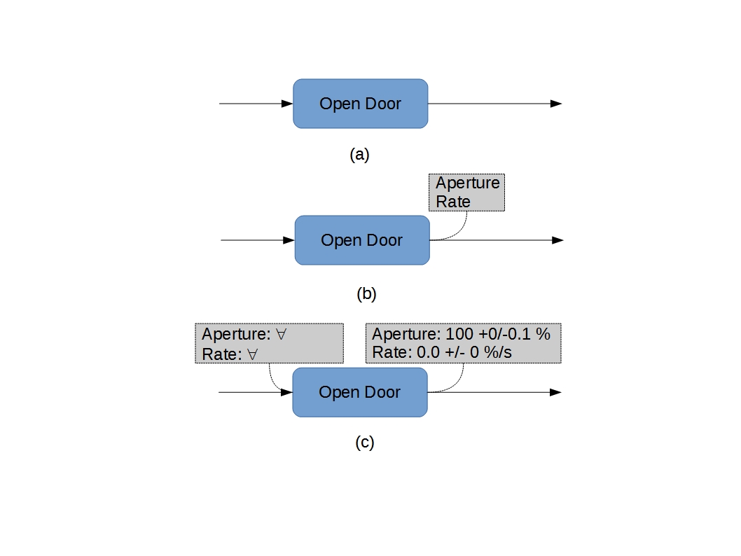
As a practical matter, an FFBD is often useful to develop block-level information incrementally (see Figure 3). This is particularly common during synthesis, and is perfectly acceptable. It is (however) important to recognize that the utility of the concept isn’t really maximized until the pertinent information has been fully developed.
Function Flows
Figure 4 shows a trivial sequence of functions. It will be noted that the blocks of parameter values are associated with the function rather than the lines between the functions. Some formats (e.g., Simulink) impose the opposite in at least some circumstances. In this context, that imposition is always incorrect9.
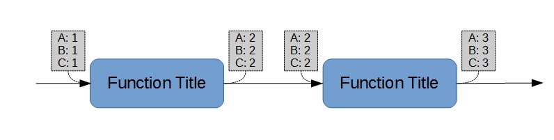
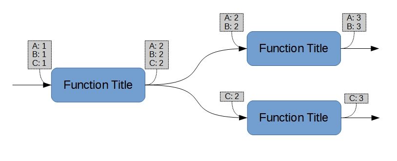
The underlying reason for associating the parameter blocks with the functions (rather than with the connecting lines) can readily be seen in Figure 5, in which the consequential parameters are distributed among their subsequent functions. No intermediate “summing” block10 is required if the parameters have been comprehensively addressed. The technical intent (“and” vs. “or”) is without ambiguity. Such blocks might, however, remain useful during evolutionary stages (e.g., sub-figures 3a and 3b).
Aside
It will be noted that the text of FM770-7811 mandates “…a statement of beginning and ending conditions, e.g., inputs, outputs, and interface requirements (both intrasystem and intersystem)…”. Mostly, all I’ve done is move some of that information into the body of the diagram to improve emphasis thereon.
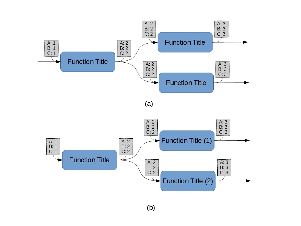
The use of parameters (and values) to differentiate parallel chains from alternative chains does not preclude “functional redundancy”12, but it does necessitate a differentiating convention for the functions such as that shown in Figure 6 (b). It should be noted that, since the Function Title is often used as an abbreviated reference, discriminating titles are usually required.
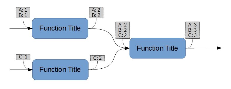
Parameters can also “merge” as they chain downstream into a single function (Figure 7). As with the complementary concept of sequencing consequential values, no ambiguity is created if the parameters are explicitly addressed on the diagram.
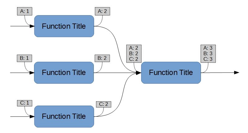
Whether upstream or downstream, however, a fully flattened set of parameters (see Figure 8) is always cause for suspicion, since it is indistinguishable from the trivial decomposition of a parent function. Such sets are often used to give the appearance of insight where none, in fact, exists. I have worked with13 people who very seriously believed that Functional Decomposition is incomplete until one Function produces exactly one consequential parameter, which is an invalid criterion.
Decomposition
In this context, decomposition is the process of identifying, for a single function14, a sequence of constituent functions that accomplishes the control as described in the superior function. The function being decomposed is often referred to as the “parent” function; each constituent function is often referred to as a “child” function. This concept is applicable to both analysis and synthesis.
With respect to the parameter values, each child function differs in scope from the parent. “Differs in scope” can mean that a parameter being controlled by a child makes a different change than it does across the parent, that a child controls a subset of the parent’s parameters, that it controls a superset of the parent’s parameters, or that it controls an altogether different set of parameters having some validated relationship with one or more the parent’s parameters.
My use of the expression “different scope” is with malice aforethought. It is important to note that commonality decisions made during synthesis might mean that a child function has greater scope than any one parent.
Furthermore, a decomposition can refer to design synthesis decisions executed in response to the parent function(s). A parent function that (for example) results in a decision to have a door can mandate the opening of that door, even if the parent function itself doesn’t mention “door”. The FFBD is a conceptual tool used in an iterative process executed with each “layer” of decomposition. Each iteration includes functional “specification”, design (synthesis), and technical analysis. Skipping the synthesis and technical analysis steps and “plunging” into functional decomposition is a bad idea that is severely deprecated here.
The decomposition process is recursive with respect to the prior description. As with any recursive algorithm, the hard part is knowing when to stop. Here, two concepts of completion are acknowledged:
(1) Within any single decomposing diagram, when all of the parent’s admitting and consequential parameters are accounted for. This does not require an exact match: explicit reparameterization between a parent and the union of its children is acceptable, as is augmentation of the parent’s parameter lists with greater detail at lower levels of the functional decomposition. This can be thought of as a “horizontal criterion”, applicable to a single step of decomposition for any single parent function.
(2) Within a hierarchy of parent/child functions, when any given child function maps to a known capability15 within the developer’s verified base of knowledge and we already have applicable experience with proving that it meets allocated requirements. This is a “vertical criterion”: we don’t decompose functions unless we lack the knowledge relevant to satisfactory implementation16.
The second (“vertical”) criterion is often lost on System Engineers, for whom the overriding concern is the avoidance of design characteristics in their work. I have (on more than one occasion) worked with SE’s who firmly believe that the SE group needs to perform Functional Analysis uniquely on every rivet in the system. This is unnecessary: experience suggests that most Structural Engineers are capable of dealing with rivets (and other fasteners) without any abstract help from the SE community. If our company insists on hiring Structural Engineers who lack such basic competence, the quicker we go out of business, the better off the prospective End User will be.
Footnotes- Arcania are common for other methods having similar objectives.[↩]
- “Old” is not a synonym for “wrong”.[↩]
- I will also apologize in advance for not always paying close enough attention.[↩]
- That is, circumstances can be “functionally discriminating”, in which case they should show up on the FFBD.[↩]
- A type of executable model.[↩]
- Which might be nothing more than prescriptive correlation models, sometimes known as “wishful thinking”.[↩]
- Another type of executable model.[↩]
- Or class of design.[↩]
- Simulink models can (however) be architected using Bus Creator and Selector blocks to achieve the desired relationship. Perverting them to do so, however, can result in unreasonably convoluted models.[↩]
- as stipulated by FM770-78[↩]
- See section 2-3.a (1) “Function Identification”.[↩]
- Distinct implementations of accomplishing the same state transition.[↩]
- …and strongly disagreed with…”[↩]
- including its parameters.[↩]
- e.g., functionality of a part, where that part can be purchased from stock without redevelopment by the original design authority.[↩]
- In other words, once we can show that we know what we’re doing from here on out, we stop with the formal functional abstractions.[↩]