My Standard Caution About Examples applies to this page.
Start with an excerpt from a general specification for retention and release devices as they’re used on deployable spacecraft mechanisms1:
The design of latching devices shall be such that peaking of resistance near the end of travel of the deployables is minimized.
Discussion
There are two ways to go, here.
One way is to “lawyer” the requirement: legacy practices would often try to establish precedent on every program that certain phrases denote Statement of Work2. Two such phrases are used in the current example: “the design…shall be such that…” and “…is minimized”. In both cases, the underlying notion is that words are being used to describe work (“design” as a verb, “minimized” as an adjective) rather than to characterize the product itself.
From a legalistic perspective, there is considerable merit to this argument. From a practical perspective, however, arguments of this type generally cause hard feelings between developer and customer. It is generally better to understand the technical intent of the provision, and determine whether a parameter can be established, and a reasonable value determined.
In this case, most latching mechanisms rely on peaking of resistance to resist unintended actuation when holding their deployable mechanism in some particular position. The latched position will typically be “beyond” the peak. When the peak is too “sharp” or too near the end of travel (or both), unit-to-unit variation (e.g., the effects of tolerances, variation in lubricity), run-to-run variation (e.g., due to wear), and the influence of environmental conditions (e.g., due to temperature or absolute humidity) can cause the peak to both “wander” and to change shape.
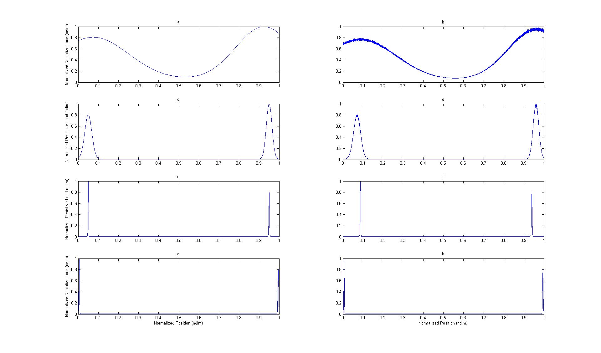
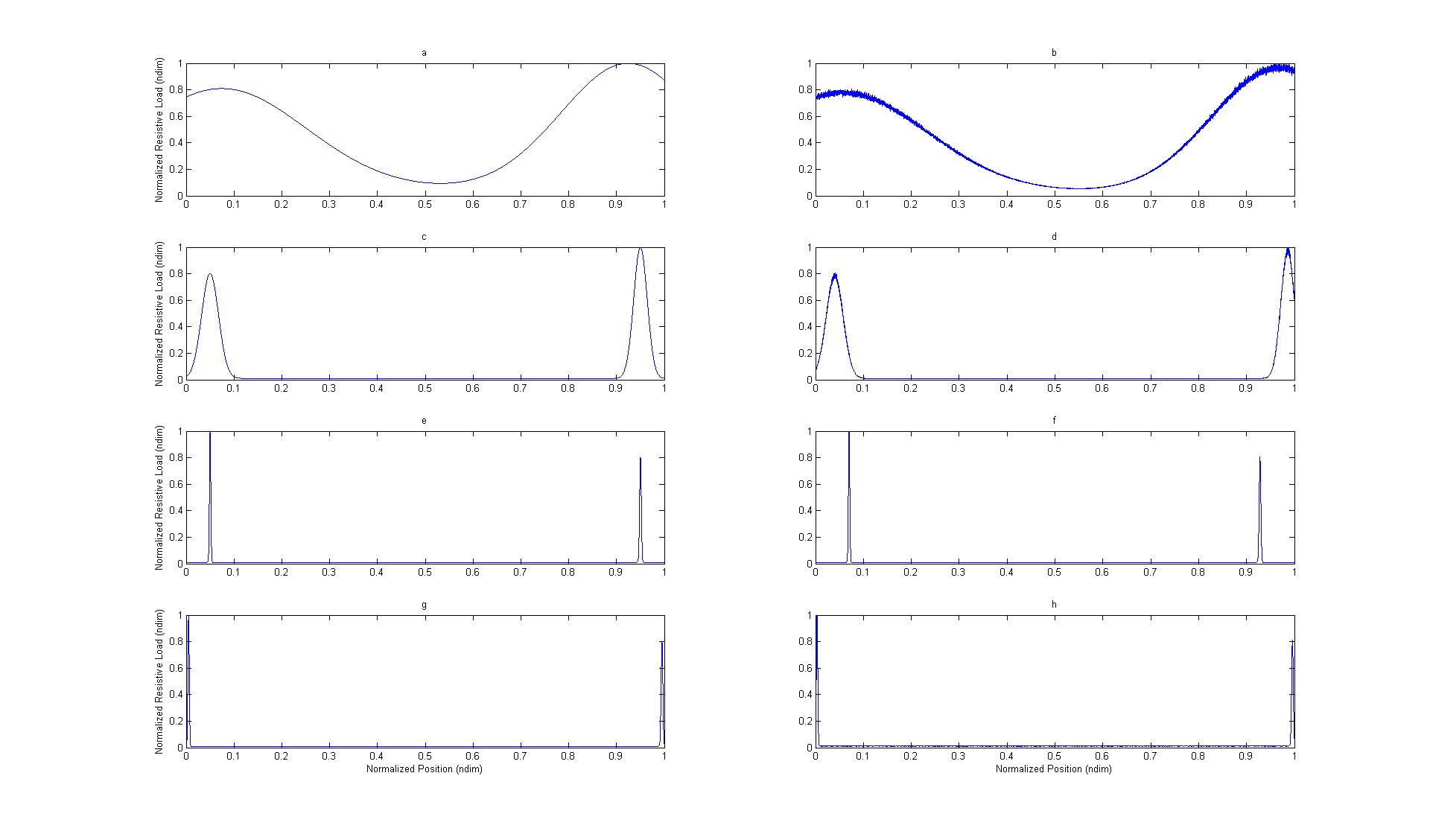
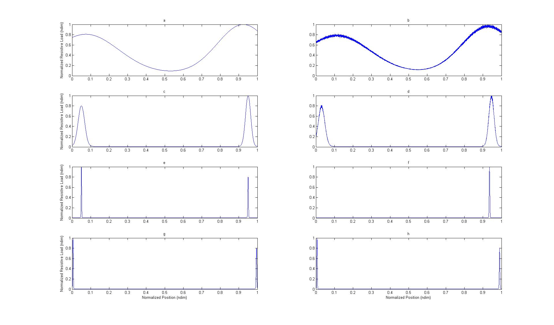
Figures 1 – 3 emulate the effects of such issues, as if for a locking mechanism that is required to hold positions at each extreme of actuation (that is, to lock on “open” and again on “close”). In all cases, the right-hand subplots (b,d,f,h) perturb the peak’s position from the left-hand subplots (a,c,e,g), as if due to (for example) variations in lubricity or slight out-of-roundness in linkage pin/hole pairs. In all cases, the nominal sharpness and location parameters of the peaks are matched within rows of subplots (a-b, c-d, e-f, g-h).
Figure 1 was randomly generated: that is, for no particular purpose but to assess the differences between the subplots.
Subsequent executions of the emulation algorithm (here) eventually produced Figure 2. Note that subplot d shows that the right-most peak does not completely decay by the time the emulated position reaches full actuation. Since the ability to withstand unlocking forces is measured by the difference between full-actuation and the peak, this particular emulation provides less margin against those loads. It may (or may not) still be adequate to the usage, depending on what other requirements have been allocated3.
Repeated execution of the emulation algorithm eventually produced subplot f of Figure 3, in which the left-side locking peak disappeared altogether, implying that a mechanism with behavior such as this would altogether fail to lock.
The point here is that tolerances (and other sources of variation) can cause significant loss of performance. The original authors are trying to alert the developer to the dangers posed by locating too sharp of a peak too near the end: having a peak that is too high above the surrounding region and too pointed can also be bad: for some designs, the theoretical contact stresses inside the locking mechanism can approach infinity. “Sharpness” alone is not the entire issue; “too near the end” by itself is also not the entire issue. However, the latching concept usually relies on peaking to effect the function: subplots a and b of all three figures would be poorly suited to most applications, having peaks that are too broad and smooth.
The best way to deal with this requirement would be to show that it is effectively redundant with other requirements that are more clearly parameterized (e.g., a well-planned “retention margin” and margin against “detrimental” yielding), assuring the customer that both extremes of the problematic spectrum have been verifiably precluded4.
Footnotes
- MIL-A-83577B, 3.2.2.2.1 [↩]
- And so, never find their way into a specification.[↩]
- The same observations (and comments) can be made for the left-side peak in subplot g, but that one’s harder to see.[↩]
- As usual, domain-specific technical insight is of considerable use.[↩]