Introduction
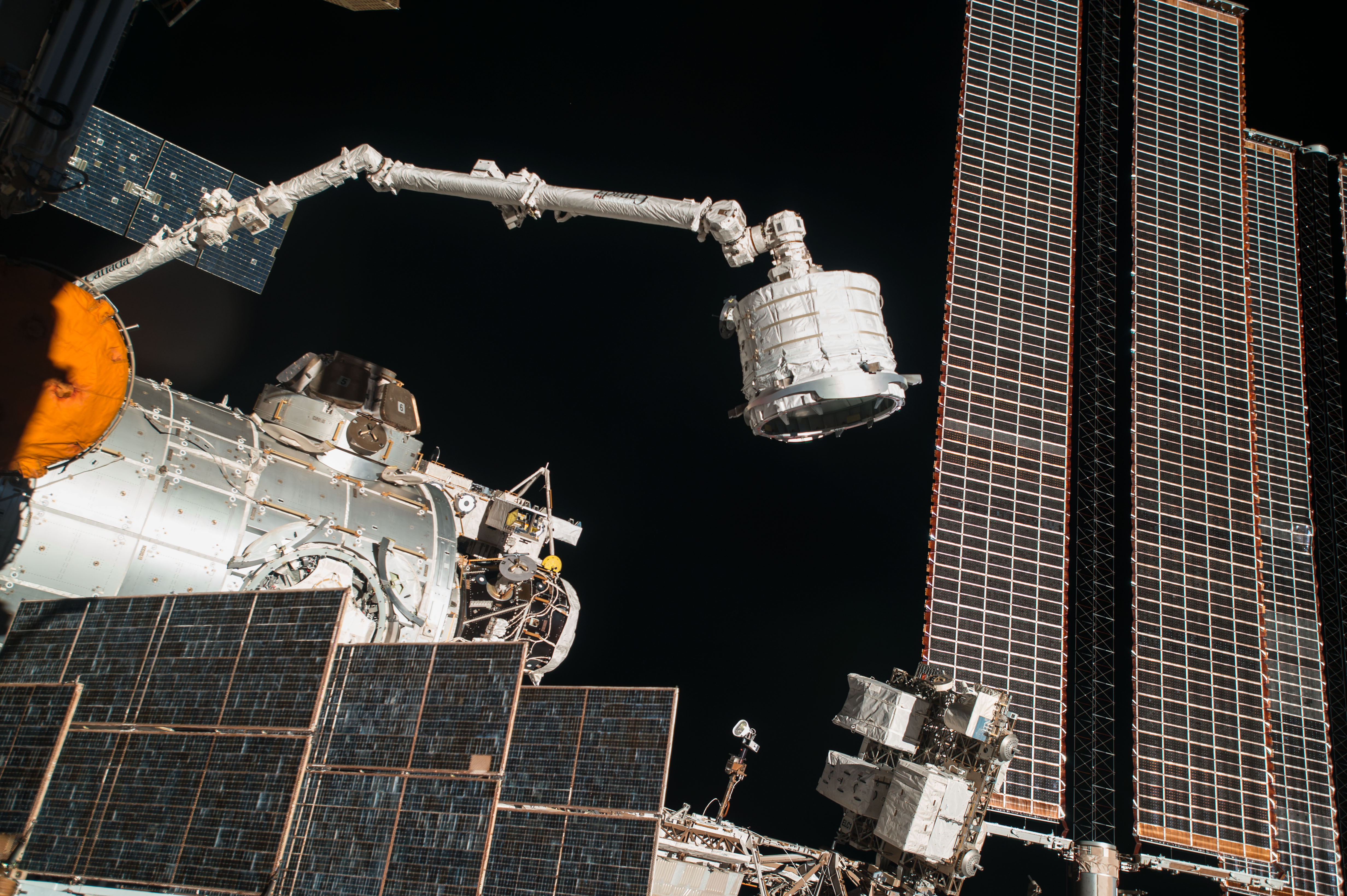
The Common Berthing Mechanism (CBM) is a structural/mechanical device that connects pressurized elements within the US Orbital Segment of the International Space Station (ISS). It is used during assembly operations, such as that shown in Figure 1, and resupply missions.
Existing in two distinct “halves”, the CBM effects and removes the Primary Structural joint between Pressurized Elements1 on orbit2. It functionally corresponds to docking ports that are used to join similar elements within the ISS Russian Orbital Segment3, and to similar mechanisms supporting on-orbit operations prior to ISS development4.
The CBM was developed by the Boeing Company during the 1990’s. The developmental effort was begun under Work Package 01 of the Space Station Freedom program (contract NAS8-50000). It was completed under Product Group 3 of the ISS program (contract NAS15-10000)5. First launch occurred with the Unity module (Node 1) aboard STS-88 (4 December 1998). Subsequent uses included most ISS Assembly flights in which a Pressurized Element was added to the US Orbital Segment, and many resupply launches by non-Russian vehicles3. At least 60 berths have been successfully accomplished on orbit as of late 2018.
Background
In the time frame of ISS development (late 1980’s to early 2000’s), the largest mass that could be lifted to orbit by NASA’s premier launch vehicle was about 56,000 lbm 6. At over 140,000 lbm7, the mass of the ISS’ Pressurized Elements alone is far more than that, requiring the ISS to be assembled on-orbit8, which was the existential requirement for the CBM.
As an assembly mechanism that unites many different internal, pressurized environments, the CBM involved multiple technical disciplines addressing both internal and external components, along with some that were unique. These ranged from determining the extremes of thermal conditions to the accommodation of a full range of flight crew measurements. For the sake of focus, summaries of several such topics are discussed here.
Conceptual Design
Being heterogamous, the two halves of the CBM operate as a single mechanism only in conjunction with each other. At least three types of CBM exist: one passive and two active. The two ACBM types are differentiated by their provisions for long-term protection to their “parent” pressurized element.
Aside
A good argument could have been made that the Type II ACBM should not have existed as a CBM variant, per se. The bumpers and covers could have simply existed as part of the next-higher-assembly parent element because their inclusion was driven by needs of their installed location having nothing to do with the functionality of assembling the ISS. The detailed design and horizontal integration of those items, however, relied on the technical skills associated with the CBM. Related organizational and programmatic considerations strongly figured into the eventual configuration identification, making the CBM an interesting example of that concept9.
Similar “considerations of convenience” resulted in vestibule closeout provisions (post-berthing) being included in the CBM/PE ICD (SSP 41004). Those provisions, however, were excluded from the CBM specifications. To the best of the author’s knowledge, no explanation for the inconsistency was ever advanced.
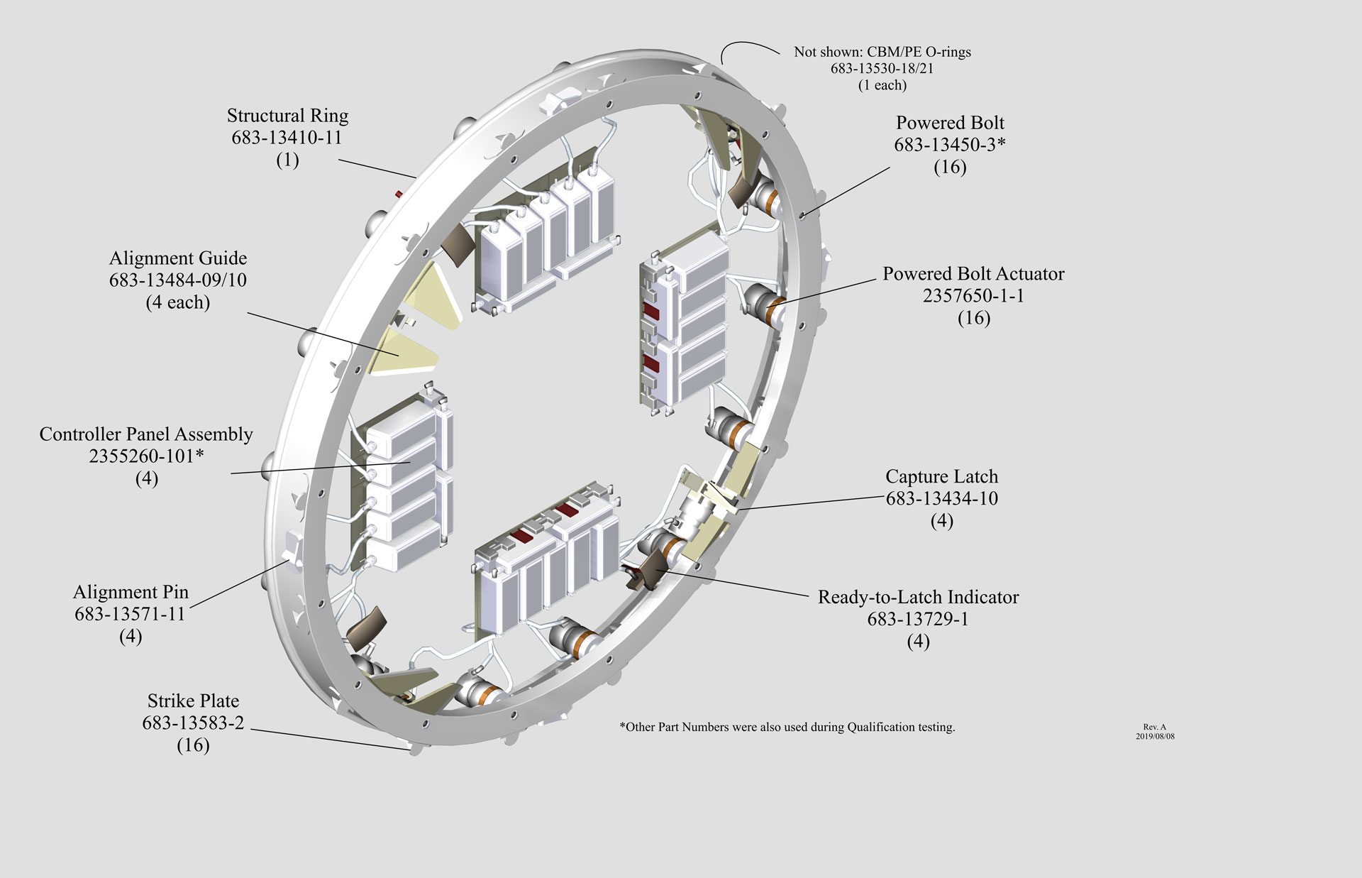
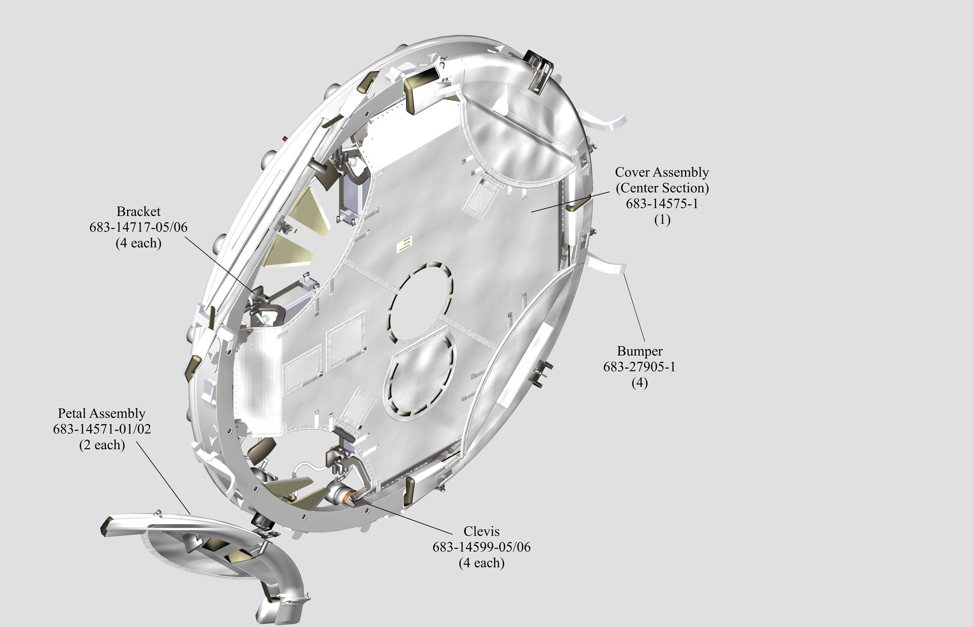
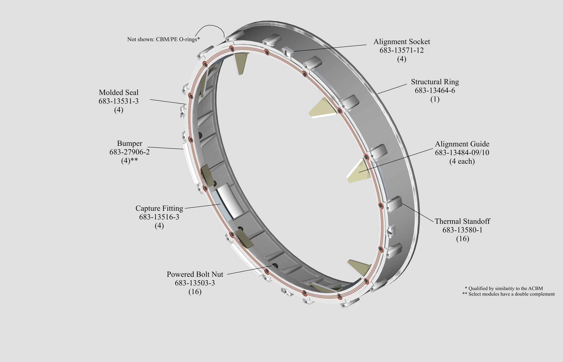
The general arrangements and major components are shown in Figures 2 and 3. With the exception of the M/D Petal Assembly, part numbers in the figures are as found in the Assembly Level Qualification Test Report (T683-13850-3) Appendix B.110.
Additional description of the conceptual design, along with a bit of insight into its evolution, is found here.
- Not all of which are pressurized in the pre-berth condition. See, for example, the Cupola, Z1 Truss, and PMA.[↩]
- NP-2015-05-022-JSC, “Reference Guide to the International Space Station, Utilization Edition” (2015), NASA. One permanent CBM joint was effected under factory conditions between Node 1 and PMA 1.[↩]
- NP-2015-05-022-JSC, op. cit. [↩][↩]
- See NSTS 21492 “Payload Bay User’s Guide”, Johnson Space Center (2000)[↩]
- S683-28943E, “Passive Common Berthing Mechanism Critical Item Development Specification” (1998), Boeing Defense and Space Group, CAGE 3A768.[↩]
- NSTS 21492, (2000) NASA (JSC). The actual mass depends on the orbital altitude and inclination of delivery.[↩]
- NP-2015-05-022-JSC, “Reference Guide to the International Space Station, Utilization Edition” (2015), NASA.[↩]
- See Dempsey, Robert, “The International Space Station: Operating an Outpost in the New Frontier”, NASA (2018), page xvii[↩]
- or, perhaps, a counter-example[↩]
- The report identifies only the moving mechanical assembly that effects the deployment; the figure relies on unpublished personal notes for the part number shown.[↩]