For the purposes of System Engineering, a model is a mathematical abstraction of a thing or situation. In this context, use of the word “mathematical” is quite broad, including (but not limited to) things like Counting, Arithmetic, Algebra, Integral Calculus, Differential Calculus, Statistics, Set Theory, Graph Theory, Topology, and various forms of General Abstract Nonsense1. Being abstractions, models focus on a selected subset of the characteristics for their subject, setting all others aside. System Engineers use models to objectively and reproducibly evaluate characteristics for all our usual motivations.
Aside (with regard to lexicon)
Words like “variable” and “value” are used on this page in their vernacular (but technical) sense rather than the senses defined elsewhere herein. The reader is cautioned to avoid confusion2.
In that context, models are comprised of expressions. An expression is a combination of symbols that can generally be classified according to three categories: “numbers”, “variables” or “operators”. In any given expression, the combination follows the rules of syntax and semantics for that expression’s declared branch of mathematics3. A model must contain at least one valid expression, and none that are invalid 4. There is no upper limit on the number of expressions in a single model. Neither do we impose a constraint on the number of mathematical branches that can be incorporated into a single model.
Expressions may be hierarchical, where the values for some of the variables might be internally evaluated based on subordinate expressions (a “sub-expression”: in effect, direction to calculate a value and substitute it into a position of the expression). We permit a subordinate expression to use a branch of mathematics different from that of the superior. Furthermore, different sub-expressions may apply to a single position under different circumstances; differentiated sub-expressions may use different branches of mathematics. There is no limit on the number of sub-expressions that may contribute to a single superior symbol. The word “expression” in the fore-going statements of this paragraph may be changed to “model” without loss of validity.
Aside
Like System Engineers, Mathematicians love to debate abstractions, of which several are contained in the preceding paragraphs. For example, I’ve glossed over differences between “operators” and “brackets” denoting the order of operations for certain branches of mathematics. A “bracket” certainly is a symbol…but the practical truth is that it is the pairing of brackets that we care about, which indicates hierarchy of process. Use of a bracket (therefore) is abstractly a means of assigning a value to the implicit expression (which might, or might not, be a sub-model in its own right) located between a pair of brackets5.
Similarly, some formal definitions of “expression” distinguish between “operator” and “function”6. As a practical matter, a function is a means of assigning a value to an implicit expression (which, again, might or might not be a sub-model in its own right).
In both cases (and several others I haven’t explicitly mentioned here), I don’t think those philosophical nuances are of great practical importance, so I’ve “abstracted them away”. What matters is that models use math (which might be pretty abstract), they have to follow the rules of the math they use, they can be hierarchically composed of sub-models and, as long as the rules are followed, we don’t require any particular model to limit itself to a single branch of mathematics throughout that model’s hierarchy.
Models can generally be separated into two flavors of interest to System Engineers: structural models identify a set and express the relationship(s) between the members of that set; algorithmic models7 define a sequence of operations in calculating values for expressions. We impose no constraint on mingling the two flavors in a single model hierarchy: we can use an algorithm (for example) to specify the members of a structural model’s set, and we can parse the symbols of an algorithmic expression into a structural model of that algorithm.
Examples of Structural Models
The identifying drawing for a piece part is an example of a structural model: among other things, it defines the physical features of a part and expresses their relationship in the form of geometry, using standard syntax and semantics (e.g., ASME Y14.5M) in support of manufacturing.
Similarly, an assembly drawing defines its constituent piece parts (usually on a Parts List) and expresses rules for 1) using their features to correctly manufacture that assembly and 2) verifying said fabrication to be acceptable. An assembly drawing is (therefore) also a structural model.
The Parts List is also a structural model, showing sets of parts that constitute the assembly. In general, the relationship shown in the Parts List is the trivial “also next assembles into”, but can also convey significant information about which parts can be substituted for one another, which is often a critical relationship driving cost and availability.
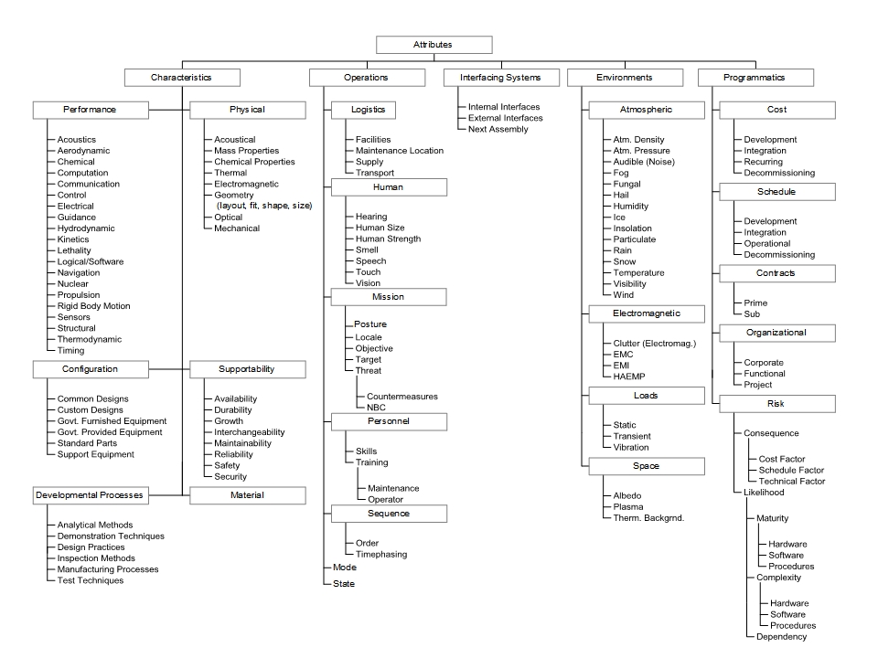
A taxonomy is a type of structural model in which things are classified according to a single set of characteristics. Different combinations of values (or ranges of values) for those characteristics are associated with each node. As we move down the taxonomy, we reduce the range of values are obtained for characteristics: children are more “specific” than their parents. Furthermore, each leaf node8 is mutually exclusive with every other node: a given item in-scope to the taxonomy belongs to exactly one node, and that node must be a leaf. The relationships between the nodes are a matter of similarity according to the range of characteristic values.
Figure 1 is a simple taxonomy, having just one characteristic: it classifies attributes according to their usage in many legacy development projects. For example, “Acoustics” is one of many concepts used to quantify Performance, which makes it a Characteristic, which makes it an Attribute. Figure 1 is just a “mental model” of how such attributes can be organized.
A Relational Database schema (see Figure 2) defines the fields for one or more “tables” of data. Each field is defined in terms of its “type” of data (e.g., integer, floating point, binary, long word, short word). Each table is defined by a unique combination of fields, where some subset of the fields (the “Primary Key”) for each table has an assuredly unique combination of values for each row in the table. Furthermore, each non-Primary Key field in that table requires the entire Primary Key in order to be sure of storing (and retrieving) the correct value of that non-Key field. Logical relationships between the tables are established when the Primary Key for one table can be found in other tables (a “Foreign Key”), such that complex outputs can be reconstructed from the stored data9. A database schema is a structural model of the data where that model complies with the rules of Set Theory.

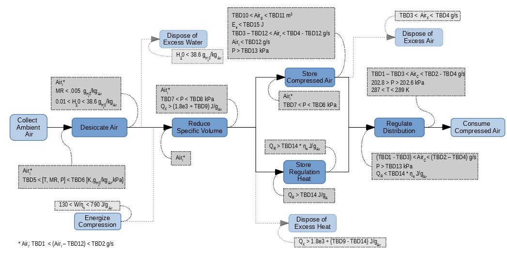
An FFBD is a structural model in the System Function Domain, identifying purposeful changes in state and the sequential relationships between them. Figure 3 shows an FFBD excerpted from the air compressor example.
Examples of Algorithmic Models
Equation 1 is a highly simplified model emulating the temperature of the UUT in the 4-bar linkage failure example during cold soak. It is an algorithmic model because 1) the algebraic order of operations govern exactly how the calculation should proceed10, and 2) it is semantically unambiguous11.
where
T(t) is the time-varying behavior of the UUT’s characteristic temperature;
T0 is the initial temperature of the UUT;
Tf is the modeled final temperature of the UUT;
Z is an arbitrary multiplier on the final temperature, as if a factor between the UUT and a cold wall;
F is an arbitrary “time constant” coefficient, making the temperature change faster or slower
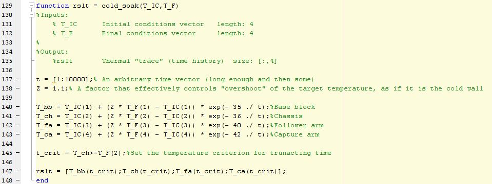
Figure 4 is an implementation of the model shown in Equation 1. It is a model in its own right, meeting the criteria specified above. The differences between the two models are that 1) the code fragment is less abstract than the equation, calculating the temperatures for four specific locations on the UUT; 2) the code is “machine executable”12, written to comply with the syntactical rules of the m-code programming environment and 3) the code uses numbers instead of a variable for the time constant. Although not readily apparent in Figure 4, the code fragment shown is actually a sub-model. When executed in sequence with other sub-models, it provides one of the time segments shown in the example.
Aside
A reasonable argument could be made that, as written, the code fragment of Figure 2 is not a valid model, because it is semantically opaque in failing to define the time constants as variables (“F”) and explaining where the numbers came from and why they were chosen. If, however, it were published along with Equation 1 (and a bit of verbiage to connect the two), then I’d still accept it as adequate.
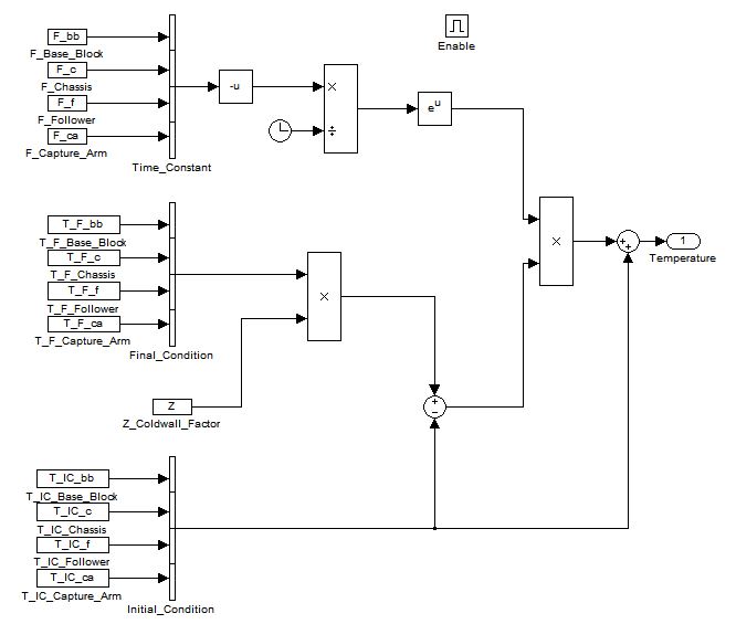
Figure 5 shows a second implementation of Equation 1. Like the code fragment, it is a machine-executable sub-model, but it runs in a commercially available ODE solver. Use of the commercial solver (however) means that Figure 5 is incomplete: the solver requires extensive configuration in order to select many important characteristics that are not properties of the phenomenon shown in Equation 1. To stand as a valid model, those configuration characteristics must (somehow) be published with the graphically-shown algorithm.
Given their appropriate configuration-controlled context, all three of the algorithmic models shown here are valid and useful. Even though they might deliver slight differences of answer, they are still objective and reproducible, amenable to review and discussion by disinterested third parties when, as, and if necessary.
Footnotes- If you’re not familiar with GAN as a term, you should probably look it up before leaping to any conclusions.[↩]
- But no apology is forthcoming![↩]
- No, that is not an example of General Abstract Nonsense![↩]
- A “valid ” expression follows the syntax and semantics for the declared branch of mathematics.[↩]
- I suspect we’d find that most compilers deal with brackets in a manner very similar to this description.[↩]
- “function” in the sense of mathematics, not in the sense of System Engineering.[↩]
- see algorithm[↩]
- That is, having no children nodes below it.[↩]
- Of course, the rules for forming Relational Databases are more complicated than how I’ve abstracted them here.[↩]
- That is, it follows the syntactical rules of algebra.[↩]
- That is, we know what the variables stand for.[↩]
- After compilation or interpretation[↩]