This article discusses the design of core characteristics of the CBM. In this context, “core” refers to the features that contribute directly to berthing and deberthing of Pressurized Elements. A detail-light description of these features can be found here. Ancillary features are discussed elsewhere.
Overview
The CBM design can be visualized as a pair of serrated rings that mate face-on. Of each pair, one is both powered and controlled, while the other is unpowered and has no degrees of control freedom. The two sides are respectively referred to as the “Active Common Berthing Mechanism” (ACBM) and “Passive Common Berthing Mechanism” (PCBM).
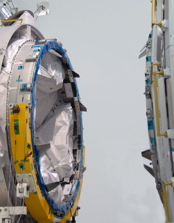
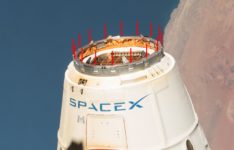
The bolt-on serrations, several of which are visible in Figure 1, mesh as the two halves are mated. They include thermal “standoffs”, alignment “guides”, “locating” pins and, on certain installations, protective bumpers. All of the serrations span the joint between the mating faces. Contact between them gradually constrains the relative alignment of the two halves during the mating event.
To the rings are mounted either 40 or 44 sub-mechanisms1, depending on the installed location of the ACBM. In either case, 40 of the sub-mechanisms span the joint between the two rings. The serrations and sub-mechanisms dynamically interact as a 45th mechanism, generating loads that are reacted into the Pressurized Elements by way of the structural rings. Interactions between the two sides occur in the form of impact, bearing, and friction loads in six degrees of kinematic freedom: three translations and three rotations.
For the benefit of the ontologically obsessive reader2, 20 of the 40 sub-mechanisms operate as actuators for the overall (45th) mechanism, which is comprised of the entire complement of hardware and software, excepting only the four “extra” mechanisms. On installations where 44 sub-mechanisms are present, four of those 20 serve a second purpose3 as actuators for the extra four sub-mechanisms, but only when there is no PCBM present.
Each of the sub-mechanisms, whether powered or passive, is considered a distinct moving mechanical assembly as defined in MIL-A-83577B4. Each is, therefore, subjected to acceptance testing on every serial number produced. No device pairs that span the ACBM/PCBM interface are ever acceptance tested together5. The two sides rarely meet except on orbit, and might have been fabricated many years apart. Formally, we’d say that there are no “matched sets” crossing the interface plane. The PCBM’s are interchangeable with respect to the ACBM, and vice versa6.
Each ring provides seals between it and the Pressurized Element to which it is mounted, and provides for sealing across the joint between the two sides of the CBM7. Components for mechanism control and for protection from launch and on-orbit environments are mounted on the rings or in close proximity to them. The details of their mounting depend on the installed location of the CBM. Location-specific details are addressed in an ICD between the CBM and the rest of the PE (SSP41004).
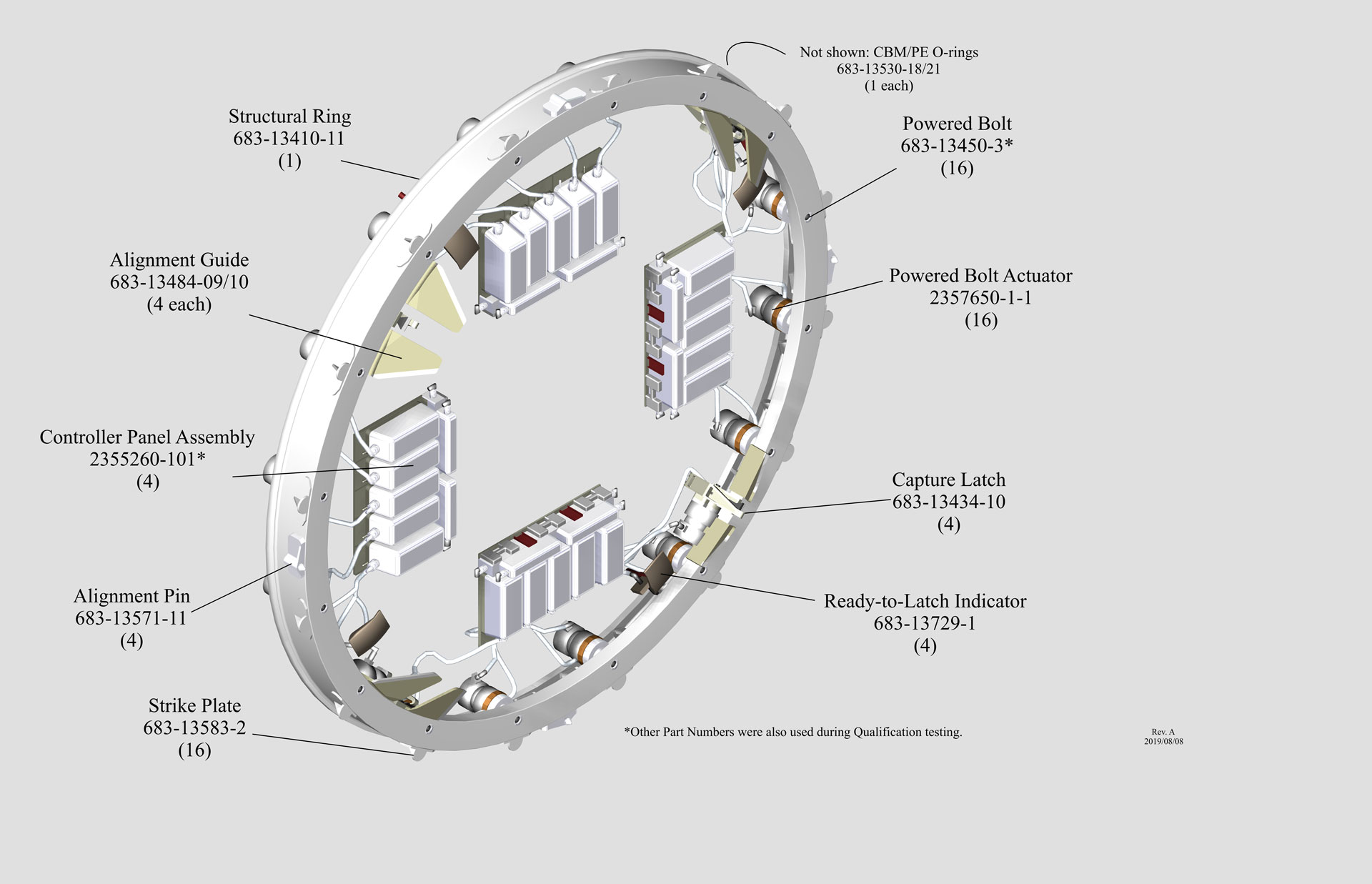
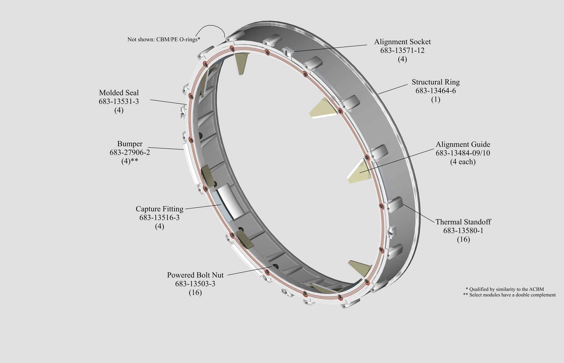
The core components of the ACBM and PCBM designs are shown by nomenclature and Qualification Part Number (P/N) in Figure 2. Table 1 pairs corresponding items across the CBM/CBM interface plane.
| Class | Nomenclature | ACBM | PCBM | ||
| Qual P/N | Qty | Qual P/N | Qty | ||
|
Structure |
Structural Ring | 683-13410-11 | 1 | 683-13480-1 | 1 |
| CBM/CBM Seal | N/A | – | 683-13531-3 | 3 | |
| Alignment Guide (L/R) | 683-13484-9/-10 | 4/4 | 683-13484-9/-10 | 4/4 | |
| Pin/Socket | 683-13571-11 | 4 | 683-13571-12 | 4 | |
| Mechanism | Powered Bolt/Nut | 683-13450-2/-38 | 16 | 683-13503-3 | 16 |
| Strikeplate/Standoff | 683-13583-2 | 16 | 683-13580-1 | 16 | |
| Ready-to-Latch Indicator | 683-13729-1 | 4 | N/A | – | |
| Capture Latch/Fitting | 683-13434-109 | 4 | 683-13516-3 | 4 | |
| Control | Controller Panel Assembly | 2356260-101/-201/-301 | 4 | N/A | – |
| Actuation | Actuator, Powered Bolt10 | 2357650-1-1 | 16 | N/A | – |
The Qualification Part Numbers (Qual. P/N) shown in the table can be different from the flight P/N. Normal Configuration Management practices require such differences of configuration to be reconciled, which means (in this context) “if the flight article is different, here’s why the qualification data still apply”. In a sense, that’s a statement of verification by similarity, independently asserted for each delivered item.
Primary Structure
Figure 3 profiles the primary structure of the vestibule wall after a bulkhead-mounted PCBM has been hard-mated to an ACBM. The most prominent features are the two aluminum alloy rings (AL2219T851 or T852), each machined from a single forging. Each ring is bolted to a Pressurized Element mounting flange11. The PCBM ring is attached by 192 bolts12, equipped with preload indicating washers. Select bolt locations are 1/64th oversize in diameter to enhance the predictability of carrying shear loads. Axial ACBM interfaces use 208 bolts of similar type and size. Radial port installations of the ACBM ring typically require a small number of additional bolts, match-drilled to carry shear.
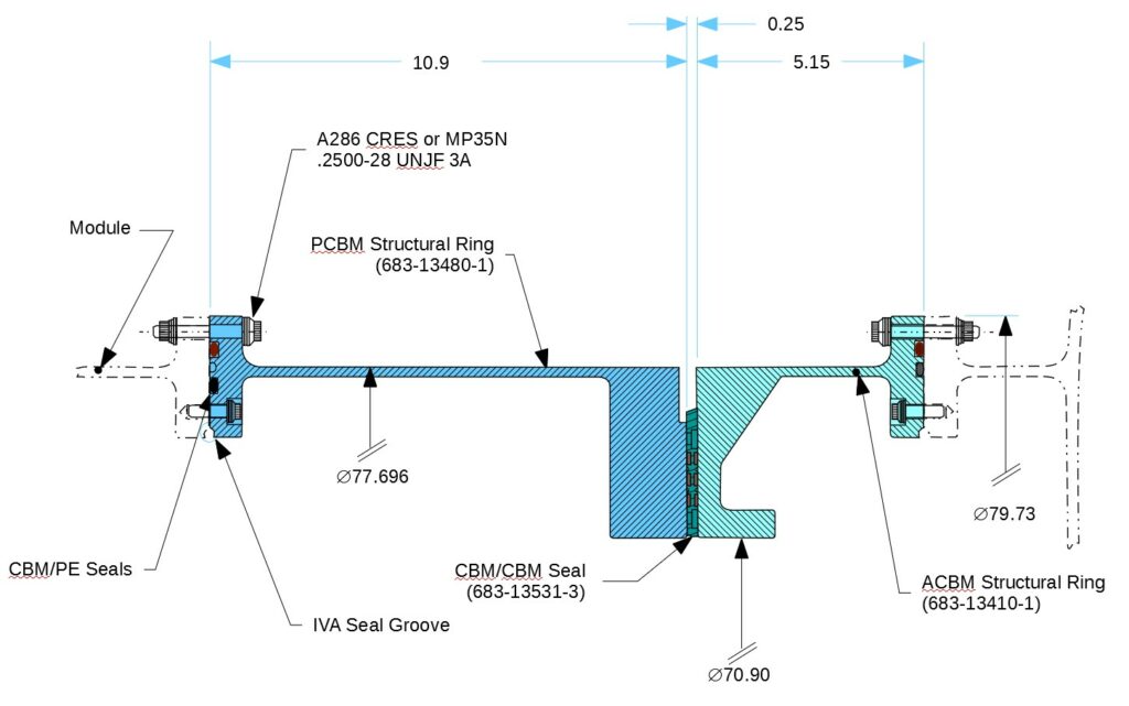
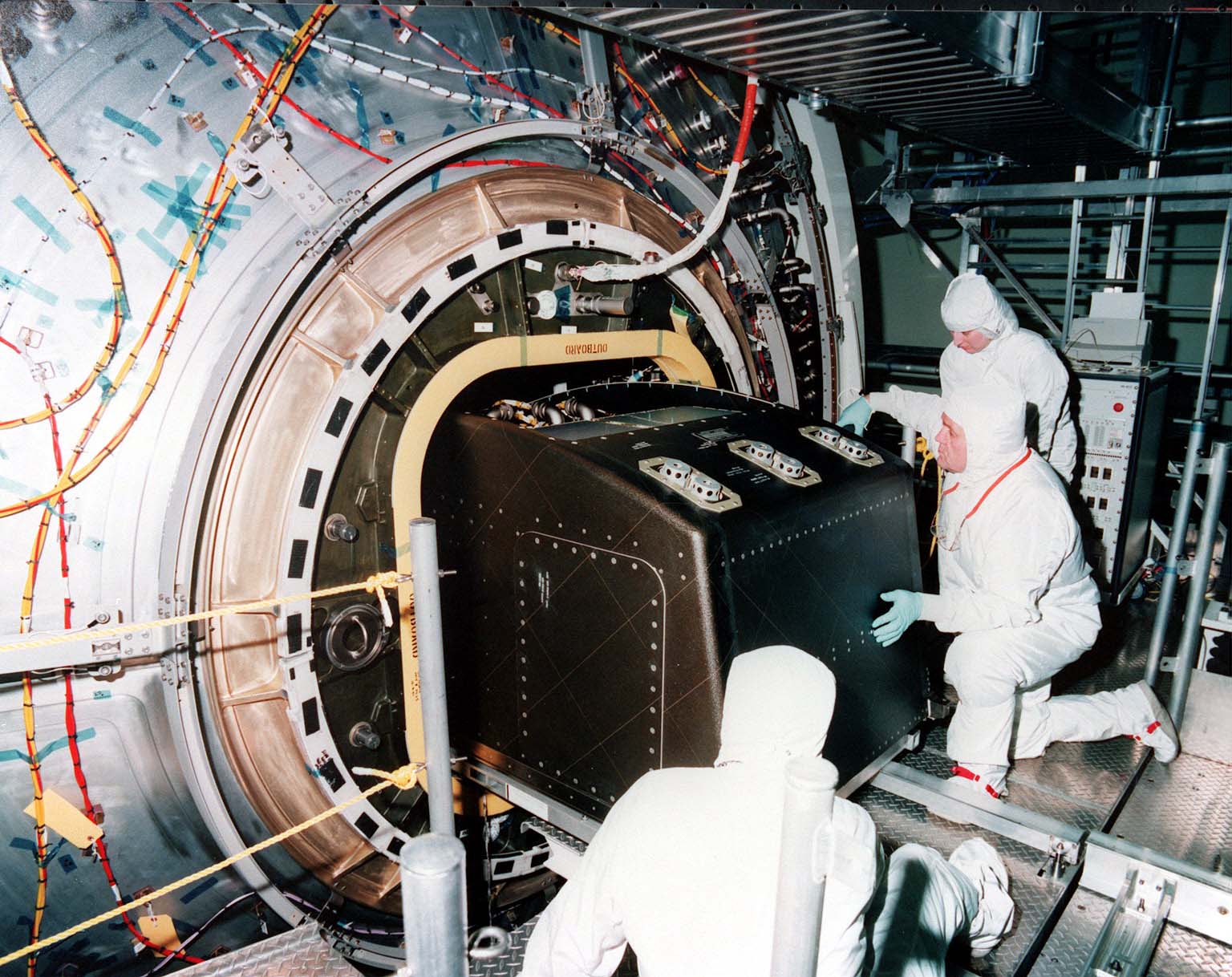
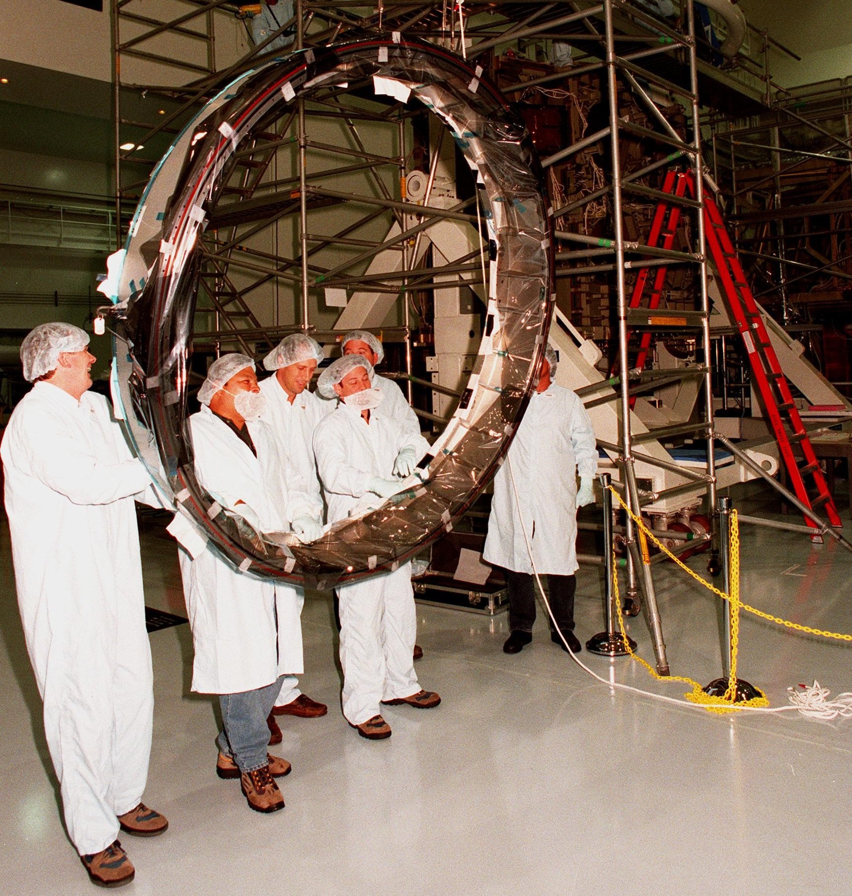
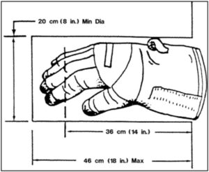
Being Primary Structure with respect to pressure, the rings were developed to meet the fracture control criteria of SSP 30558. The leak-check port makes it possible to verify the integrity of the mated interface on orbit13. A few basic dimensions are included in Figure 3, but a sense of scale is more intuitively accessible from Figure 4. The diameter of the rings was sized to accommodate the diagonal dimension of large payloads passing through the 50″-square hatch in both factory and orbital operations, as shown in Figure 5.
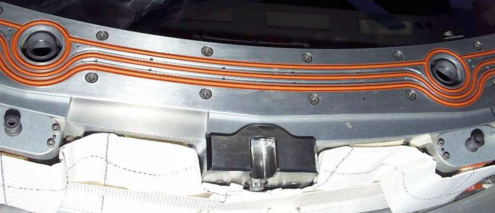
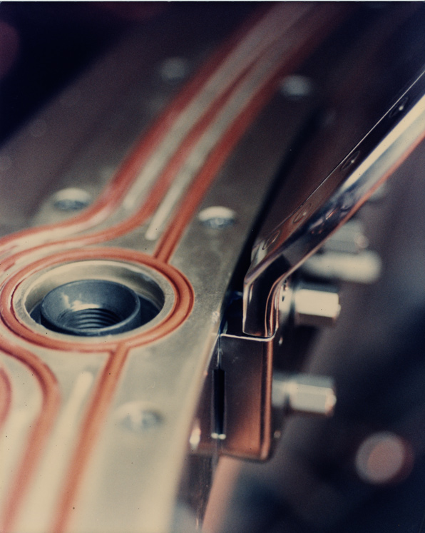
At either end of the mated vestibule, two simple o-rings seal the factory joint between tee flange and inboard flange (see Figure 6). Two different o-ring materials are paired at each inboard joint: one is flourocarbon, the other Silicon. Each bead is, by itself, sufficient to seal the joint. The different materials have different susceptibility to environmental conditions14, decreasing the system’s sensitivity to unforeseeable circumstances.
The seal at the CBM/CBM interface, shown in Figure 7, is a proprietary Parker “Gask-o-Seal” design that combines certain conceptual properties of o-rings and gaskets. Each segment is based on a metallic retainer15, as shown in Figure 8. Each of the retainer’s machined grooves are filled with an elastomer, cured in place. Each elastomeric bead runs around both ends of the segment and along both faces16.
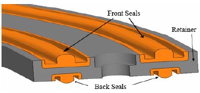
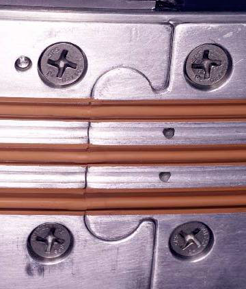
Four Gask-o-seal segments abutt to cover the face of the PCBM’s outboard flange. The segment-segment joints are implemented as the high-precision “dovetail” seen in Figure 9. Each segment is bolted to the PCBM ring face during assembly, compressing the underside of the beads and (simultaneously) the dovetail joints. The assembly can be leak-tested to verify pressure integrity.
The design can be implemented with different elastomers. The PCBM was qualified with both Silicone and Viton, to be used depending on the launch circumstances: Silicon is more tolerant of low temperatures and atomic oxygen, where Viton is more robust with respect to scrubbing under load.
Being depot-replaceable and covering the face of the flange, the segments constitute a sacrificial layer of protection for the PCBM ring. The utility of being able to customize and replace this exposed piece of sacrificial interface hardware should be readily apparent to the reader from Figure 10.
All three large-diameter seals can be augmented on orbit with seals installed after the vestibule is pressurized. The compression plates and beads of the augmenting seals are shown in Figure 11. These “IVA seals” are a contingency, installed only when on-orbit leak testing identifies a primary seal as having failed17. In all three cases, the IVA seal is implemented as an elastomeric seal compressed by a plate spanning the interface, installed in the outward radial direction. Also in all three cases, the IVA seal does not fully “replace” the primary seal, having fewer beads between atmosphere and the high vacuum of space.
Powered Bolt and Nut
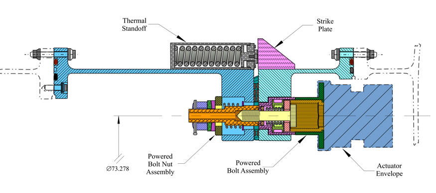
The general arrangement of the PCBM’s ring, seal, Powered Bolt Nut and Thermal Standoff can be seen on Figure 6. Figure 11’s cut through the mated vestibule at one of 16 equally-spaced radial planes shows how they align with their counterparts on the ACBM18. In the figure, the CBM/CBM seal and the Thermal Standoff are shown at their maximum compression. The outboard flanges of the rings are shown in the figure as if fully “conformed” and pressure-stabilized. Mechanical loads applied during the “rigidization phase” to reach this “hard-mate” condition are applied by the Powered Bolt reacting through the Powered Bolt Nut. The early stage of bolt operation (“nut acquisition”), however, is actually the last stage of the Capture function as that function is defined by the specifications.
Seen in Figure 12, the Powered Bolt is a stand-alone mechanism comprised of several precision piece-parts. The shaft, of 5/8″ nominal diameter, is machined from Inconel 718. Nominally about 3″ long, it is partially threaded at a pitch of 1/18 inch per MIL-S-8879C19. The threaded portion is required to be no more than 0.967 inch, but providing at least 18.3 full turns of engagement in the follower20. The follower21, nominally 0.167″ thick, is internally threaded to receive the shaft. The helical spring being behind the follower (toward the head of the bolt), the shaft will advance when turned clockwise22, because the follower cannot retreat23. The helical spring also ensures re-engagement of shaft threads into the follower when the bolt is retracted from the nut. A wave spring behind the head of the bolt provides moderate thrust of short stroke to ensure engagement of the follower by the lead threads on the shaft24 as a fully-retracted shaft begins its advance.
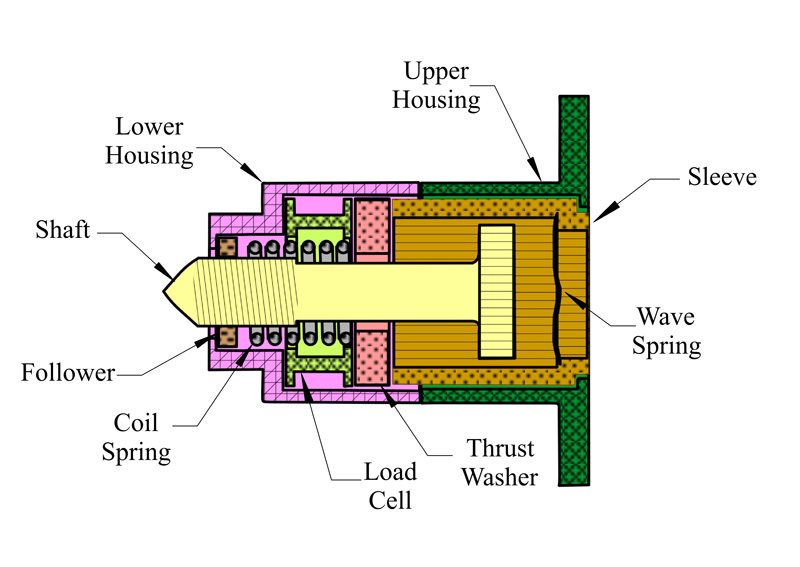
The externally-grooved head of the shaft is one element of a concentric gear train between the actuator and the bolt shaft. It interfaces with the internally-grooved sleeve, which in turn interfaces with the toothed output shaft of the actuator25. As long as the threaded end of the rotating shaft is engaged with an internally threaded device26, the shaft head will slide along the grooves until it bears on the thrust washer which, in turn, bears on the load cell.
Absent a PCBM nut, the bolt can nominally advance about 0.7″ before unthreading from (“dropping”) the follower towards the bolt head. Dropping the follower toward that end of the shaft determines the approximate maximum reach of the bolt toward the nut during berthing operations, starting from the fully retracted position. The relative location of that starting position can be seen in the foreground of Figure 13. In practice, however, the reach is limited to less than 0.7″ because of misalignments, for which the nut compensates.
The nut assembly, shown in Figure 14, is a Nitronic-60 “encapsulated” nut floating in a spring-loaded plate. The assembly accommodates four local degrees of freedom27 in the aggregate of rigid body translations and rotations between the rings, and manufacturing tolerances and distortions of the rings. See the discussion on CBM requirements for more detail on distortions, which were treated as derived requirements during the final iterations of CBM development.
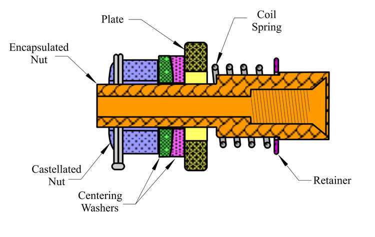
The in-plane float of an un-tilted nut varies between about 1/10″ and 1/5″, depending on the azimuth of motion perpendicular to the nominal centerline of the Encapsulated Nut28. The bolt continues to turn while the nut slides and tilts29 into coaxiality with the bolt shaft, so some of the bolt’s stroke is consumed during the alignment process.
The axis of the nut is not necessarily parallel to the axis of the bolt shaft when the bolt starts to turn. It can be misaligned (both shift and tilt) due to pressure- and thermally-induced distortions of the ACBM ring and, to a lesser extent, of the PCBM ring. There can also be residual misalignment at the end of Capture Latch operation. When the nut is tilted with respect to the bolt shaft, its translation capability is reduced in proportion to the dimensions of the nut’s internal piece parts. When misaligned, the nut often tilts dynamically (at least a bit) as the tip of the bolt contacts the entry chamfer of the nut30. Tip contact forces, reacted by the nut’s helical spring, cause the tilt to self-correct as the two sets of threads engage.
The relative local roll angle between the lead threads of the nut and those of the (respective) acquiring bolt is a random variable, treated as having uniform distribution in rotation of the bolt shaft31. This has the analytical effect of further reducing the probable reach of the bolt. The roll angle (number of turns) to engagement and tolerance stacks are all non-deterministic, as is (therefore) the actual reach of the bolt during operation. Being stochastic, qualification of bolt reach was by Monte Carlo Analysis, which was validated by assembly-level qualification testing using several customized, worst-case components.
Loads and Loading
The Powered Bolt is primarily subject to axial loads and, when being actuated, torque loads32. Axial load is dominated by compression of the CBM/CBM seal and, in radial port installations, by conformance of pressure-distorted outboard flanges into face-to-face contact. To a lesser extent, changes in temperature after the hard mate can also impact loads in the bolt. Torque loads are entirely due to the actuator that tightens the bolt into the nut during the rigidization phase of operation.
Technically, the bolt/nut load path is “preloaded” during assembly, meaning that the initial load is sufficient to preclude subsequent separation of the interface plane under any foreseeable external load event, including the effect of all uncertainties. This means the bolt has to be “torqued” enough to prevent separation, and has to be strong enough to withstand the combined effect of preload and torque at the instant of completing the installation. That combination is usually (but not always) the limit condition experienced by a preloaded bolt and, therefore, the qualification condition.
Aside
A normal preloaded joint more or less divides subsequent external loads according to the ratio of bolt stiffness to bolted element stiffness, but only until separation of the joint. After separation, all additional load goes into the bolt. In most cases, that leads quickly to breakage of the bolt. Separation is, therefore, usually considered a “failed” condition.
The CBM/CBM joint, however, is not a “normal bolted joint”. Loading of the bolt is “eccentric”: the flanges are not as wide, with respect to the diameter of the bolt shaft, as is typically practiced by structural Engineers, and the radius of the bolt circle is less than the radius of the center of contact pressure between the two outboard flanges. The mated flanges try to “peel open” about an axis parallel to the tangent of the bolt circle at the location of each bolt. They also try to peel about the radial line at each bolt location; that is, the ring-ring gap “smiles” between the bolts, more so on the outside of the ring than on the inside. The margin-of-safety analysis was nonlinear and not amenable to typical stress analysis practices. The deflections were a significant issue in the sizing of the CBM/CBM seal heights, and in analysis of their performance (having very non-uniform compression).
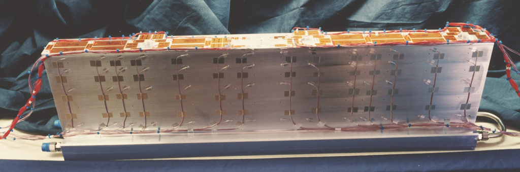
The residual deflections (after bolting to full preload) also made it difficult to estimate the heat transfer across the joint. The “floating” nature of the Gask-o-seal before berthing also isolated the PCBM ring face from the natural environment. This thermal interface was the subject of dedicated thermal contact resistance testing during development (see Figure 15), measuring the power required to hold a given temperature on one side of the interface against liquid nitrogen cooling on the other. Such tests are conducted under high vacuum to minimize the effect of alternative heat transfer paths.
Taken together, these issues correctly suggest that the bolt and nut were not really designed as if they were isolated components as implied by the present description. It was really the “joint” that was designed33: the mechanism characteristics were designed to achieve that state. That same mindset is reflected in the order of exposition for this article.
Being a preloaded bolt, the design was contractually required to comply with NSTS 08307 “Criteria for Preloaded Bolts”. Table 2 extracts criteria from that reference for establishing the preload during bolt operation34. The uncertainties expressed in the table for preloading by torque do not include the uncertainty of actually measuring torque, which can be substantial.
| Preloading Control Method | Uncertainty |
| Torque, unlubricated bolts | ±35% |
| Torque, cad-plated bolts | ±30% |
| Torque, lubricated bolts | ±25% |
| Hydraulic tensioner | ±15% |
| Preload indicating washers | ±10% |
| Ultrasonic | ±10% |
| Elongation measurement | ±5% |
| Instrumented bolts | ±5% |
| NOTE: If the bolt is torqued from the head, application specific testing to determine the preload is strongly recommended. Typical uncertainty may also be determined this way. If experience and/or test data justifies it, however, an additional uncertainty may simply be added to the above typical preload uncertainties. This method must be justified to, and approved by, the appropriate NASA center. |
|
Torque requirements on the actuator followed from successive consideration of the uncertainties of Table 235. Figure 16 shows an iterative Design Analysis Cycle to simplistically explain how several important design aspects interact. Of the four features shown, material changes had only a minor impact. Although sizing changes are listed as possible in the chart, they were limited to minor adjustments for reasons both technical and programmatic.
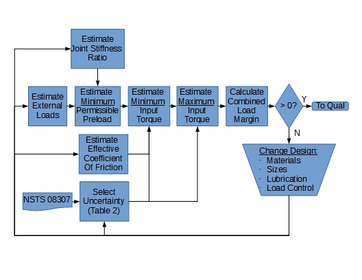
Without significant changes to material or sizing, the design converged to a nominal preload of 19,300 lbf for a maximum input torque of 1600 in-lbf. In the context of parameterization as developed here, these comprise a vector-valued quantification of the preloading function. Lubrication and instrumentation mitigated the preload issue, but (of course) created new issues to be resolved.
Lubrication
Contact-critical surfaces of the Powered Bolt and Nut are dry-film lubricated with a proprietary molybdenum disulfide compound. The treated surfaces include the underside of the bolt head and the thrust washer36, the bolt thread, the nut thread, and the nut’s washer37. The selection and characterization of the lubricant’s performance was a significant issue during development: lubrication, as it turns out, is a sword having at least two edges.
NASA TM-8655638 contains a thorough discussion of how, when, why, and where to use the various types of lubricants that were available in the CBM’s developmental timeframe. Although much research has been accomplished since then, it remains a relevant reference for the development (and understanding) of spacecraft mechanisms. Detailed review of that technical material is left to the interested reader, save for the following observation about dry film lubricants: “…environmental conditions and the operating characteristics of the system being lubricated can drastically affect the film.” Table 3 supports that observation, reporting Torque Coefficient for bolt/nut pairs under several circumstances.
| Test | Condition | Min | Max | Mean | Std | Cycles | Notes |
| Component Qual | Ambient | 0.081 | 0.100 | 0.091 | 0.010 | 13 | 2 |
| Component Qual | Vacuum | 0.031 | 0.050 | 0.048 | .004 | 49 | 2 |
| Assembly Level Qual | Ambient | 0.054 | 0.189 | 0.076 | 0.026 | 64 | 3,4 |
| Assembly Level Qual | Vacuum | 0.024 | 0.161 | 0.058 | 0.035 | 94 | 3,5 |
| Assembly Level Qual | Vacuum | 0.024 | 0.074 | 0.042 | 0.012 | 74 | 3,6 |
| Notes:
(1) In all cases, both the bolt and nut assemblies had passed individual Acceptance Testing (AT) under both ambient and vacuum condition before these data were collected. AT includes aggressive run-in testing to expose infant mortality, if present for the individual UUT. Also, none of the data in this table propagate experimental uncertainty into subsequent conclusions in the discussion39. The cycle counts are aggregated across all units reported in the test documentation. (2) Compiled from T683-85131-1 Revision New, 10/12/98, CAGE 3A768. Runs executed on three different bolt/nut pairs. Loads and torques used to calculate TC were generated by Test Support Equipment, and reported directly. The reference diameter for TC calculation is derived from T683-13850-1 , Section 5.2.2 (see Note 3). (3) Sampled from T683-13850-1 Revision New, 10/12/98, CAGE 3A768. Loads and torques were generated by the UUT to calculate TC, having larger experimental uncertainty than the component qualification test setup (see Note 2). Load and TC were reported directly. (4) The run count includes all ambient runs reported, including bolt/nut pairs exhibiting signs of early wear-out. (5) The statistics include vacuum runs 8-13, which were sufficient to stabilize the standard deviation within three significant digits. Many more runs could have been included, but little additional information would be contributed pertinent to the present discussion. The statistics shown on this row include bolt/nut pairs that subsequently wore out. (6) The statistics on this row exclude bolt/nut pairs exhibiting signs of early wear-out as developed in the subsequent discussion. |
|||||||
Aside
As used here, Torque Coefficient is a similarity parameter describing friction, being a scaled ratio of torque to load:
where
τ ≡ Indicated Torque
D ≡ Reference Diameter (Head/Thrust Washer)
F ≡ Maximum Indicated Preload
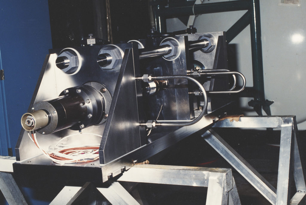
Table 4 shows four analytical cases that can be developed from the data sets in Table 3, with TC2 at two standard deviations40. Neither of the limit cases were adequate for engineering purposes: the component performance can both undershoot and overshoot more than the rest of the CBM design could tolerate. Even the (non-conservative) use of a mean-value-TC for sizing is too low to reliably maintain contact between the outboard flanges: the load to conform radial port distortions, depress the thermal standoff, and compress the CBM/CBM seal is about 10,500 lbf41. The consideration of uncertainty in measuring torque on orbit, not addressed in either Table 3 or Table 4, further exacerbates the range of preloads when controlling by torque alone.
| Case | Sizing | Delivered | ||
|---|---|---|---|---|
| TC1 | Torque | TC2 | Preload | |
| Limit Preload | 0.128 | 1544 in-lbf | 0.050 | 49,408 lbf |
| Limit Separation | 0.050 | 603 in-lbf | 0.128 | 7,540 lbf |
| Mean TC1, low TC2 | 0.058 | 699 in-lbf | 0.050 | 22,388 lbf |
| Mean TC1, high TC2 | 0.058 | 699 in-lbf | 0.128 | 8,737 lbf |
Powered Bolt Instrumentation
The implicit message of Table 442 was derived from slightly different numbers discovered in less-formal development testing. It was one of two factors leading to the inclusion of a load cell as a feature of the design.
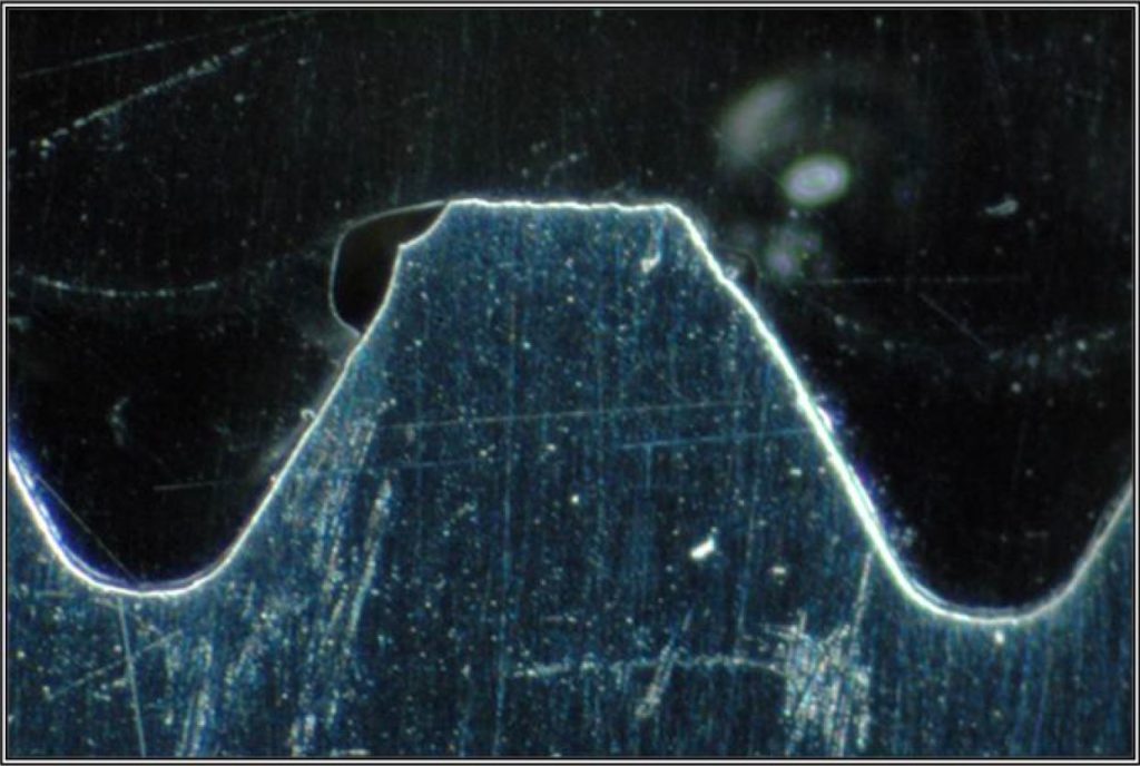
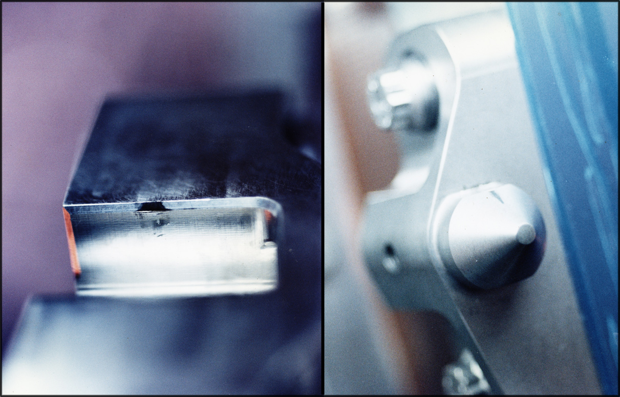
The second issue, hinted at in the notes of Table 3, was the detection of early wear-out on orbit, which can occur at every contact surface interface within and between the bolt and nut. Root causes of early wear-out include (but are not limited to) imperfect application of lubricant, and the imperfect fabrication and preparation of the parent material (see Figure 18, which is taken from Sievers and Warden43).
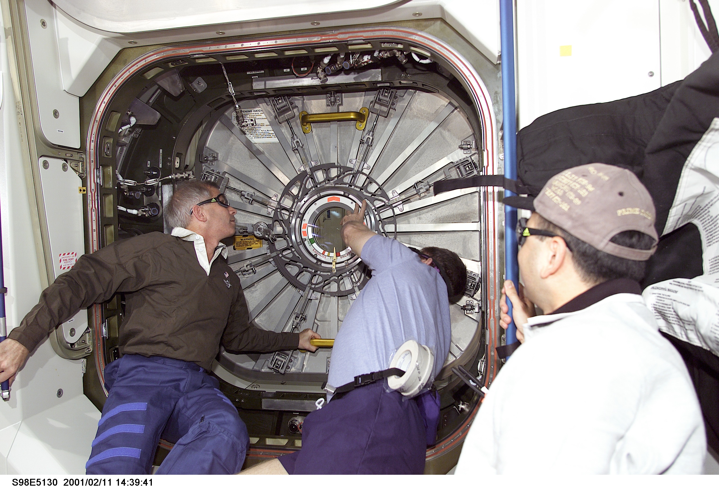
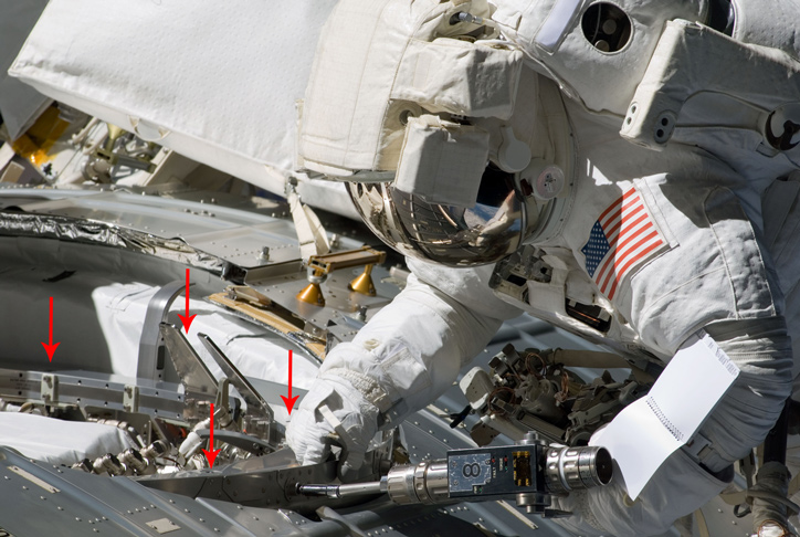
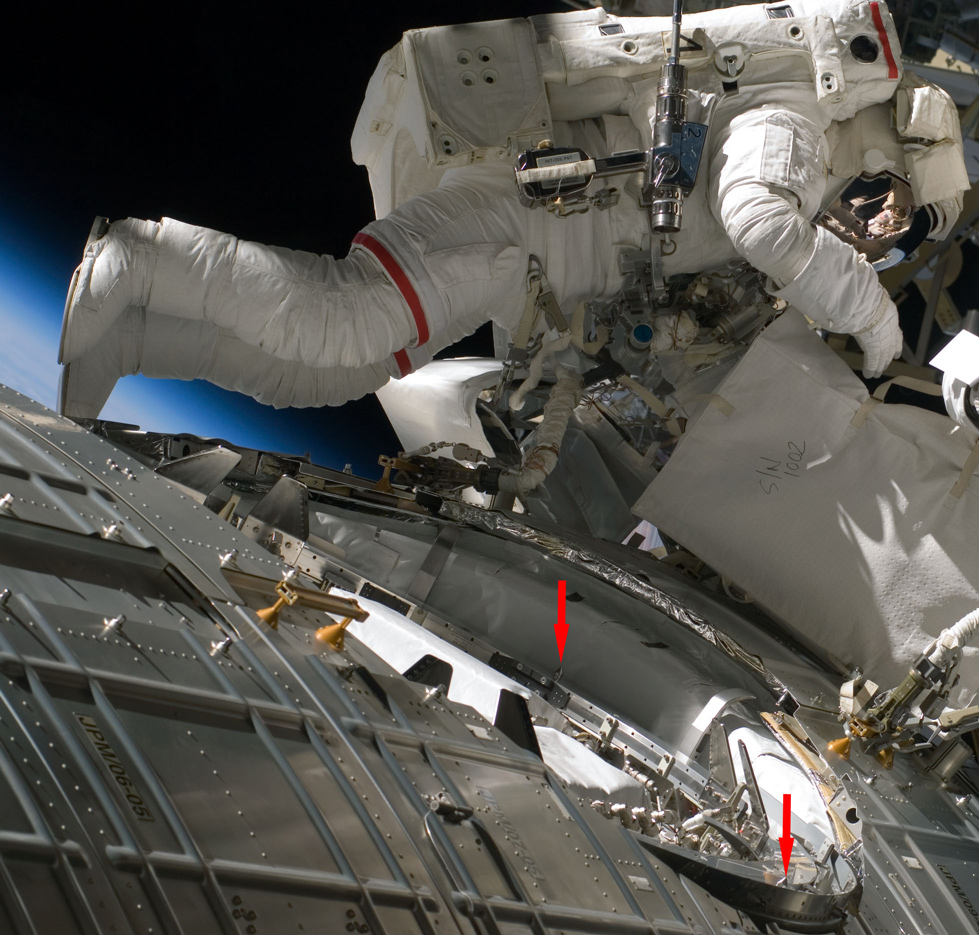
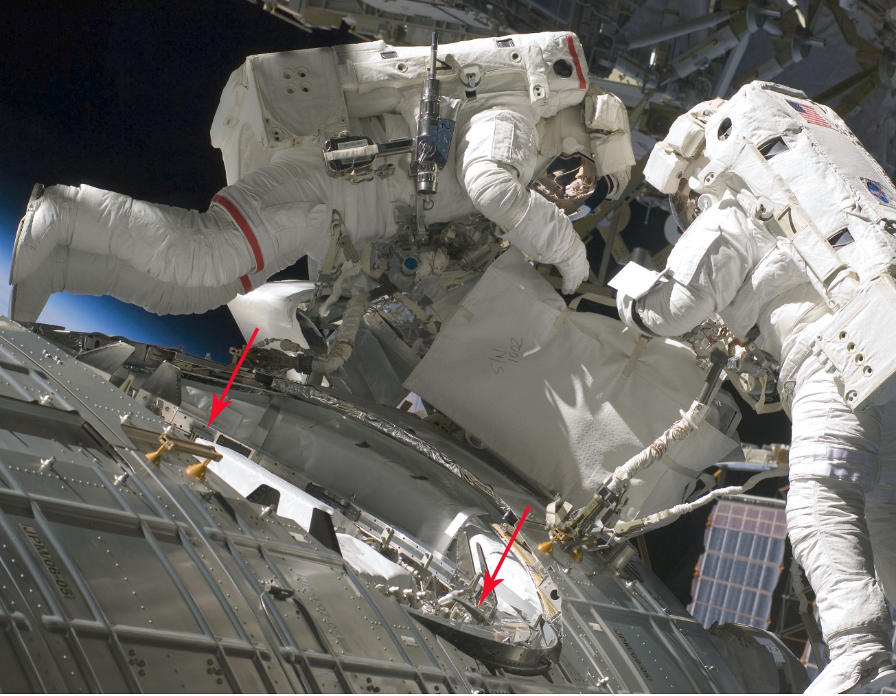
The prediction, detection, and management of wear-out was crucial to the long-term use of CBM in support of logistics activity44. As difficult as IVA access to the bolt and nut is45, EVA access is far worse. Figures 19 and 20, given the dimensions shown in Figures 3 and 10, barely hint at the issues to be addressed under EVA circumstances. Neither do they address the consequences of failure: getting hung up on the way to establishing a pressurized vestibule would constitute at least a mission-critical failure; under some circumstances, it could be catastrophic to the entire ISS.
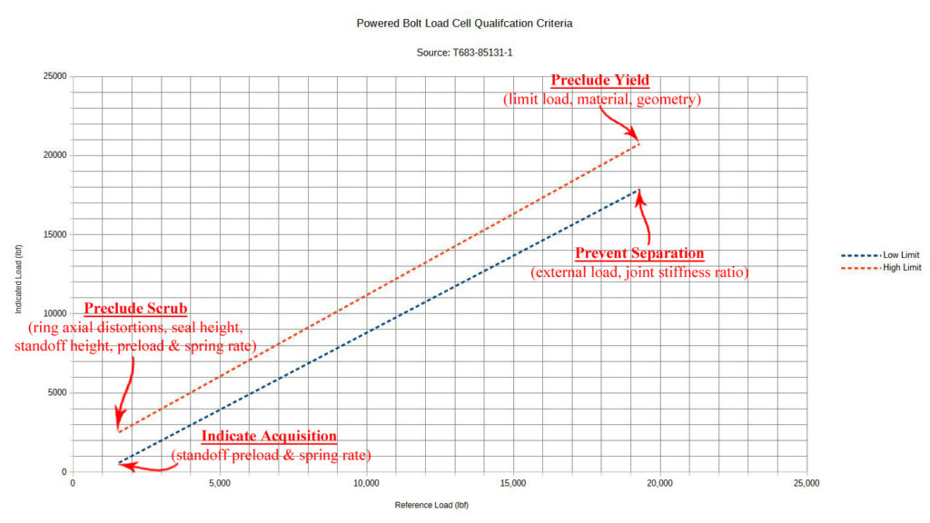
The load cell directly mitigates the potential for needing EVA access under the outboard flange during the repeated use of any given CBM over the life of the ISS. As depicted in the cross-section of Figure 11, it is a strain-gauged, toroidal I-beam. Unit-to-unit variation in fabrication of the torus and installation of gauges required custom “trimming” of the gauage’s output with a resister to bring the uncertainty46 within acceptable tolerances. The trimming criteria, and the parameters that influenced them, are shown in Figure 2147.
Without the load cell, the only objective evidence of wear out on orbit would have been the number of turns on the bolt, counted from some “hard” zero point48, in comparison to the torque. The load cell provides the capability to predict wear-out far enough in advance of failure that the bolts and nuts can be removed and replaced IVA as a matter of standard procedure, instead of emergency procedure. As of this writing (2018), replacement has occurred just twice in over 1000 on-orbit bolt actuations to full preload.
The annotations on Figure 21 are intended to clearly show that load cell performance was a significant “point of integration” for the CBM. The on-orbit variation of gap between the rings at the initial condition for acquisition of nuts by bolts created significant uncertainty in that integration exercise. The gap, which varies with with installed location, position around the ring, and loads induced by the tug-of-war between the CBM and the RMS, is residual after capture latch actuation completes. The initial stroke of the bolt brings the rings into parallel, effects a near-uniform insertion of alignment pins into sockets, and compresses the thermal standoffs just enough to signal the operators of readiness to proceed beyond initial nut acquisition without risking damage to the CBM/CBM seal.
Alignment Pin and Socket
The load path through rings, seals, bolts, and nuts carries axial and bending loads across the ACBM/PCBM interface. In theory, shear and torsion loads across that interface cannot be accommodated by those components. Formally, they’re carried by bearing between the Alignment Pin and Socket on the ACBM and PCBM, respectively.
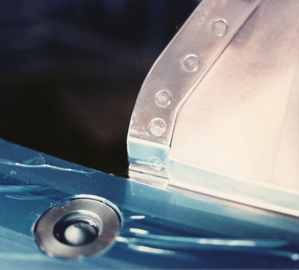
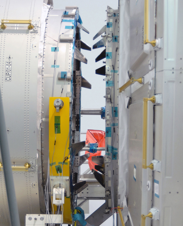
On-orbit photographs of the mated pin and socket are difficult to find, because they’re small and the joint is usually covered. The pin is about 3/4″ thick and protrudes almost 3/4″ above the face of the ACBM ring. The faces of the bases for both pin and socket sit slightly below the face of their respective sides of the interface plane49, to ensure they don’t bear on each other at hard mate. Figure 22 highlights one of four pin/socket pairs approaching a mated position during pre-flight operations on the Cupola and Node 3.
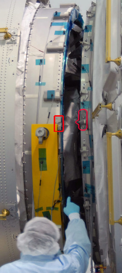
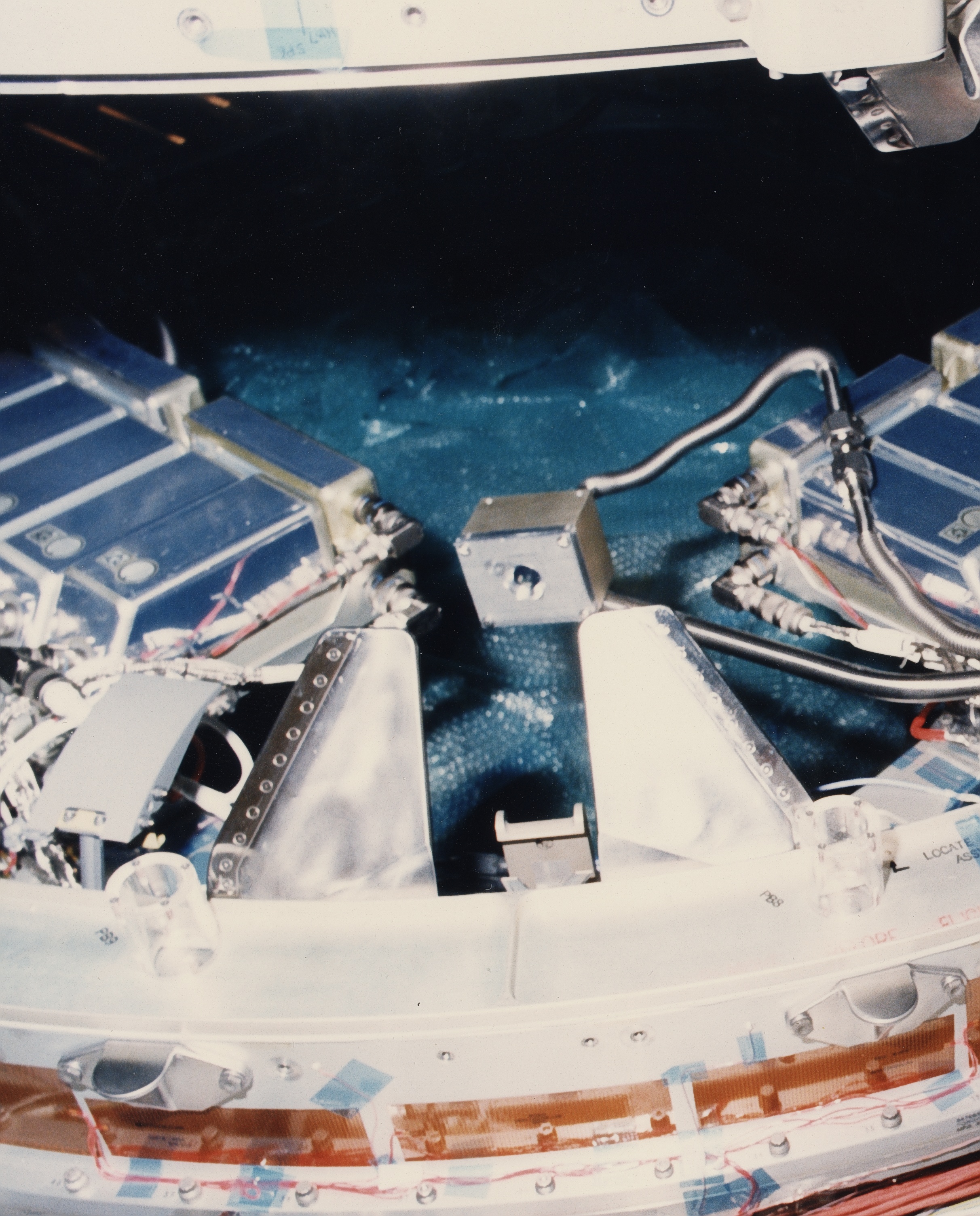
Figure 23 provides a better sense of scale for the protuberance of the pin above the interface plane in a rare photograph of the mated condition where no socket is present. An unmated socket is prominently visible in Figure 6, above.
The geometric profiles of pin and socket are driven by limit loads in shear and torsion at the ACBM/PCBM joint while hard mated. All other features are driven by horizontal integration with CBM components that are active during the capture event.
Aside
In reality, friction forces between the ACBM ring and the Gask-o-seal substrate will carry much, and possibly all, of the shear and torsion. Such load paths are not reliably quantifiable, however, so credit for them is not always taken in formal limit load analysis.
Four pin/socket pairs cross the interface plane, located at 0°, 90°, 180°, and 270°50. The locations, two of which are indicated in Figure 24, were selected on the basis of the near-zero tangential deflection at those azimuths on Node radial ports: the “socket” is actually a slot, which accommodates distortion in the local radial direction, but not in the tangential direction. Those specific locations make the alignment between rings on highly-deflected radial port ACBM locations nearly identical to that of minimally-deflected axial port ACBM locations. These positions also effectively constitute a cruciform contact surface51 rather than four pegs in four holes.
Using a root-sum-square tolerance approach, each pin has about 0.015″ (± 0.004) of total tangential gap within its respective socket. This defines the maximum theoretical scrub that a PCBM’s Gask-o-seal can have on the face of a hard-mated ACBM ring during limit shear or torsion52. It also establishes the upper limit on “ledge” to be accommodated by the CBM/CBM IVA seal spanning from between the two outboard flanges.
Like the performance of the Powered Bolt’s load cell, the physical characteristics of the pin/socket interface53 were a significant point of integration within the CBM. They control ACBM/PCBM alignment to match the ledge-spanning capability of the IVA seal, as noted above. During the first stage of capture, constraining contact is handed off from guide/guide to pin/socket. The related loads originate in the latch, for which actuator torque limits and mechanical advantage near closure were both tailored to negotiate the introduction of pin to socket.
The compliance of the nut/bolt interface is related to the pin/socket dimensioning scheme and to the coefficient of friction between them. As the wear patterns in Figure 25 show, the contact stresses can be substantial during insertion and alignment: precise coordination54 of the shoulder height on the pin with the height of the Thermal Standoff and with the final position of the Capture Latch were required in order to manage the interface. The contact surfaces were left unlubricated to mitigate the potential for deposition of debris in the near vicinity of the CBM/CBM seal and its mating flange face.
First-Stage Capture Components
Thermal Stand-off and Strikeplate
The Thermal Stand-off, seen in Figure 11’s cut-away, is a preloaded spring55 attached to the outside of the PCBM’s structural ring. Loads from the stand-off are reacted into the strikeplate56, also identified in Figure 11, bolted to the outside of the ACBM’s ring. Together, the stand-off and strikeplate provide a discrete57 surface during the first stage of capture. One pair is located radially outboard from each Powered Bolt/Nut, as marked in Figure 26. On radial ports, the strikeplate also provides a footing for the Deployable M/D Cover when no PCBM is present.
As shown in Figure 27, the discrete surface is located a little more than 1/8″ axially outboard of the PCBM’s Gask-o-seal substrate. The spring rate is orders of magnitude less than that of the rings’ outboard flanges, so is compliant relative to the forces that can be generated by the Powered Bolt. It is, however, quite hard relative to forces that can be generated by the Capture Latch.
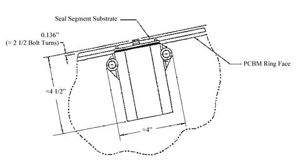
The height of the stand-off’s preloaded head is sized to establish clear separation between the crown of the CBM/CBM seal and the face of the ACBM’s outboard flange during thermal equalization hold. The sizing includes allowance for the aggregate of pressure-induced distortions on both sides of the interface plane. The height was also closely coordinated with design of the Capture Latch to avoid trying to compress the head at the end of latch operation, and with the hand-off to the pin/socket constraint from guide/guide constraint as the two CBM halves mesh.
Alignment Guide
The Alignment Guides impose a “hard constraint” on the trajectory that a PCBM can follow as it approaches an ACBM. Each guide is highly polished Nitronic-60 contact edge riveted to a titanium base58. Like the pins and sockets, on-orbit photographs of meshed guides are hard to come by: Figure 28 shows both sides of the CBM/CBM interfaces just as the guides start to mesh during pre-flight payload assembly operations.
Standing about 5″ above the axial face of the outboard flange, each guide spans just under 14° along the flange’s inner face. Two distinct guide designs exist, the left- and right-hand versions being mirror images of each other. Four of each “hand” are found on each of the two CBM halves. Spanning 31° from one contact edge to another, each left/right pair on the ACBM fits between a corresponding pair on the PCBM. The PCBM pair spans 50° between the “outer” (non-contact) faces59.
Guides are designed for contact on their respective contact edges, only. Close inspection of Figure 29 shows relief on the radially-outer surface, precluding contact between the guide and the inner corner of the opposing ring. The relief along that “back” side of the guide can be clearly seen on Figure 30. Additional relief is visible under the mounting face of the guide to mitigate the potential for scratching of the IVA seal “land” during installation.
Like the pins interacting with sockets, the guides create a cruciform contact surface. This surface, however, is oriented 45°60 from the pin/socket contact surface. Minutiae of the guide shoulder geometry were designed in concert with the minute geometry of the pin/socket interface to effect a smooth hand-off between the two sets of constraints. Also like the pins and sockets, and for the same reasons, the contact edges are not dry film lubricated61.
Unlike the pin/socket contact surface, many features of the guide/guide contact surface were established in response to issues that were themselves outside the scope of CBM development:
– The height and angle of the guides about the local tangential axis accommodate the diameter of the NSTS Payload Bay “dynamic envelope”. Their location62 was selected to avoid any need for EVA deployment63.
– The tip-width and shoulder height were sized to accommodate initial meshing of the guides, given the controllability of an SRMS operated by a trained astronaut.
– Clearance between the shoulders was sized to render unfeasible any SRMS operation below that point, reducing the credibility of damage to the CBM/CBM seal (and related surfaces) while maneuvering the PCBM-equipped element to the “capture” position64.
– The strength and stiffness of the “blade” and, therefore, the material, were selected on the basis of estimated loads arising from the SRMS in “joint run-away” (an SRMS failure mode). These loads were difficult to accurately forecast at the time, and the final material (titanium) was very conservatively chosen.
– The contact stress capability65 of the guide contact edge was designed to accommodate high forces exerted by Capture Latches66 when they were operating with a nominal “test mode” (limped) SRMS.
Issues related to the controllability of the SRMS were, in particular, developed in iteration with astronaut-in-the-loop simulation of the RMS operation, following their initially-specified requirements.
Capture Latch and Capture Fitting
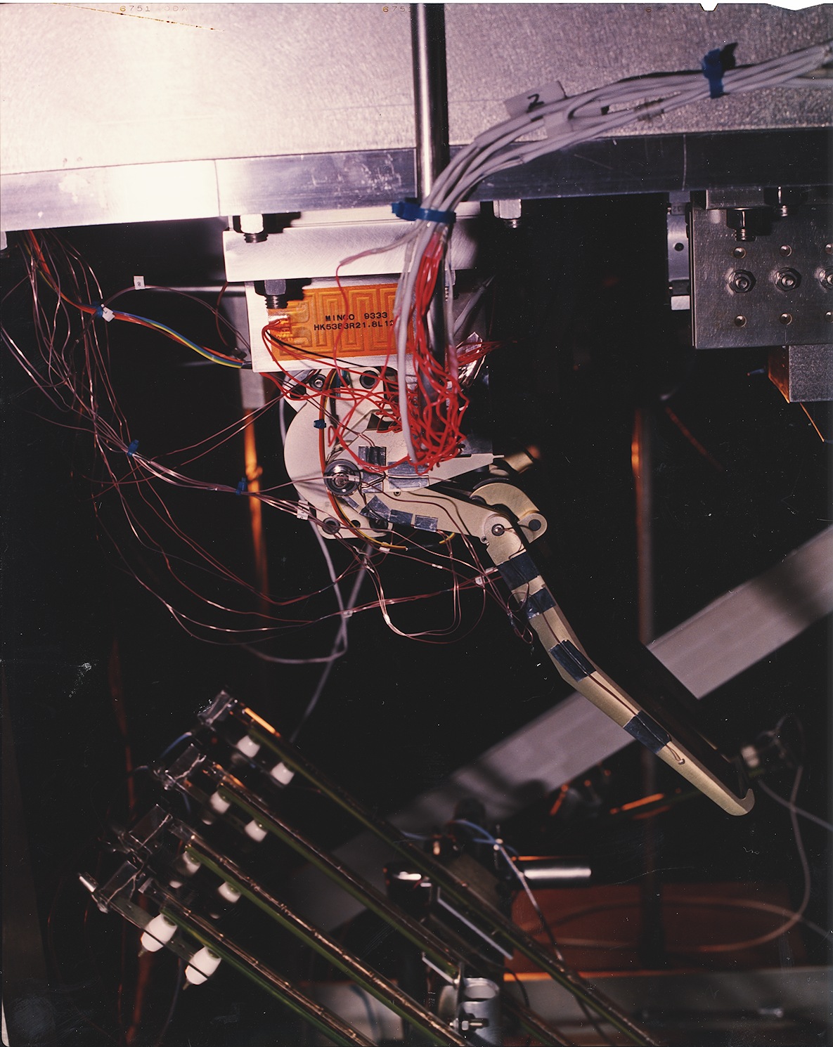
The CBM Capture Latch applies forces to bring the two halves into good enough alignment in close enough proximity for the Powered Bolts to acquire their respective nuts and finish the berth. The mechanism incorporates a contact switch to indicate full closure. A test unit, outfitted with test-unique thermocouples and strain gauges, is shown in Figure 3167.
Aside
The name “Capture Latch” is a bit of a misnomer. The word “latch”, usually means something that joins two pieces together, and then mechanically holds them that way against some expectation of external loads, without further attention from the operator. Examples of everyday acquaintance include latches for doors, gates, and suitcases.
The CBM Capture Latch doesn’t do that. Once the motor turns off at the end of the stroke, there’s no “prevailing” mechanical latching force. Only the motor’s backdrive will resist any external loads that might be applied. In reality, the Capture “Latch” is more accurately thought of as an actuator that moves the PCBM from a random initial position to a predetermined region of greater uniformity in closer proximity to the ACBM.
Kinematics
The CBM Capture Latch is a rotating four-bar linkage that is bolted to the inner-radial face of the ACBM outboard flange. The links of the latch are identified in Figure 31.
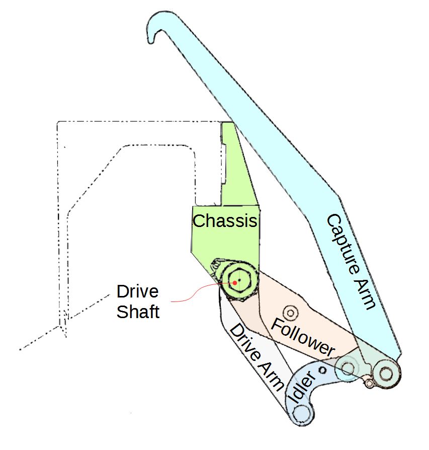
Like many Moving Mechanical Assemblies, the latch can be described as having several frames of reference. Understanding the relationship between the frames is half the battle of understanding how the mechanism moves. Figure 32 shows five different kinematic frames:
(1) The latch tip frame is defined here as a polar coordinate system. Only the radial distances are shown on the figure, the angle having an arbitrary zero reference. In practice, this frame might more easily lend itself to analysis if expressed in rectangular coordinates, but is more easily shown as it is here.
(2) The drive arm frame is fixed with respect to the latch tip frame, but shifted to the center of the drive shaft rotation. The drive arm is fixed to the shaft, so rotates in this frame. The angles shown in the figure (ranging from 0 to 205) measure the position of the draft shaft in this frame.
(3) The follower frame’s center is coincident with the drive arm frame, but rotates with respect to it. The drive arm and follower can have different angles about the drive shaft, and the angles shown in the figure measure the position of the follower.
(4) The capture arm frame is attached to, and moves with, the remote end of the follower68.
(5) The idler frame is attached to, and moves with, the remote end of the drive arm.
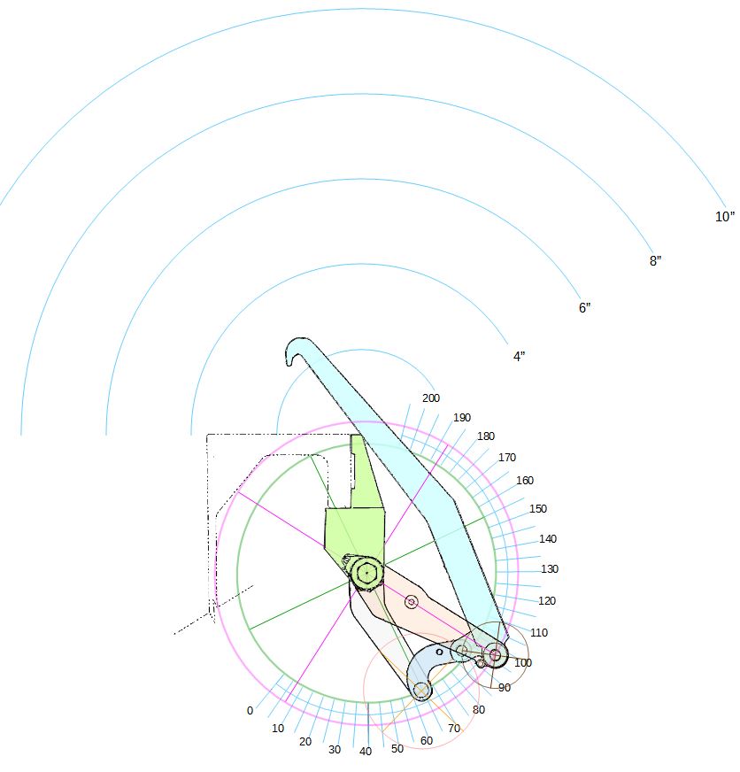
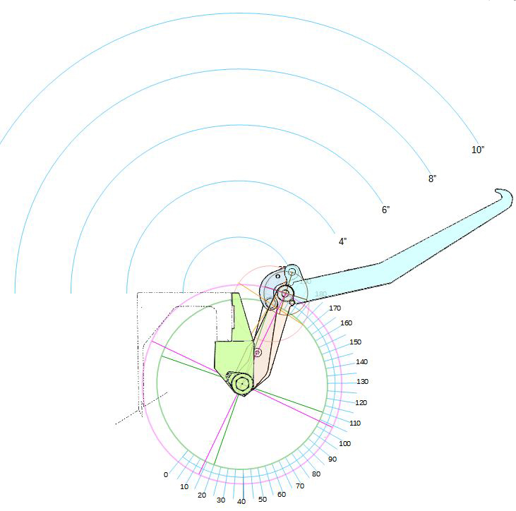
Each arm rotates around the pins through the joints at either end. It doesn’t really matter which end is used as the center of the frame of reference for any given link. The figure attaches a circle in each reference frame for each “remote” pin’s rotation about the frame’s “zero” reference. When articulating the latch, each remote pin has to stay on its respective circle. That logic is illustrated in Figure 33, as if the tip (being engaged with the fitting) had been pulled toward the center of the ACBM ring by a PCBM fitting. Note that the drive arm position is the same in Figures 33 and 34: the rotating drive arm is an independent degree of freedom compared to the rest of the angles between links.
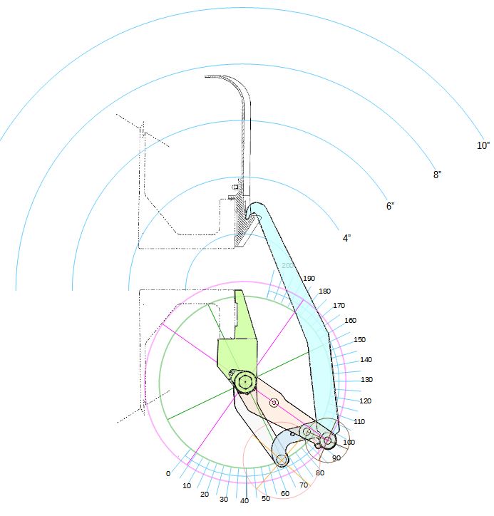
The extensive sweep of the capture arm during the capture stroke is evident from the near-deployed condition shown in Figure 34. The linkage is spring-loaded to force an outboard motion of the latch tip when the actuator begins to rotate toward closure. Its precise trajectory depends on what the tip encounters during the capture stroke:
– If a PCBM’s Capture Fitting is at the edge of the capture envelope, the hook on the tip will engage with the hook on the fitting, pulling it towards the ACBM ring. The latch tip will “pop and hop” tangentially along the fitting until roll and translations between the ACBM and PCBM are eliminated. The tangential load required for that motion originates from the latch itself, acting through the angled contact between Alignment Guides.
– If a Capture Fitting is within the capture envelope, the tip of the latch will hit the “shield” above the fitting, then slide down it until engaging with the hook on the fitting.
– If, on Node radial ports, nothing is within the designated capture envelope, the hook will engage with the trigger of an M/D Cover, closing the cover over the ACBM flange.
– If nothing is present the tip will simply flop over the face of the ring, eventually closing between the near-by ACBM Alignment Guides.
– Under all other circumstances, the tip will follow whatever constraint it encounters until something bad happens.
Loads
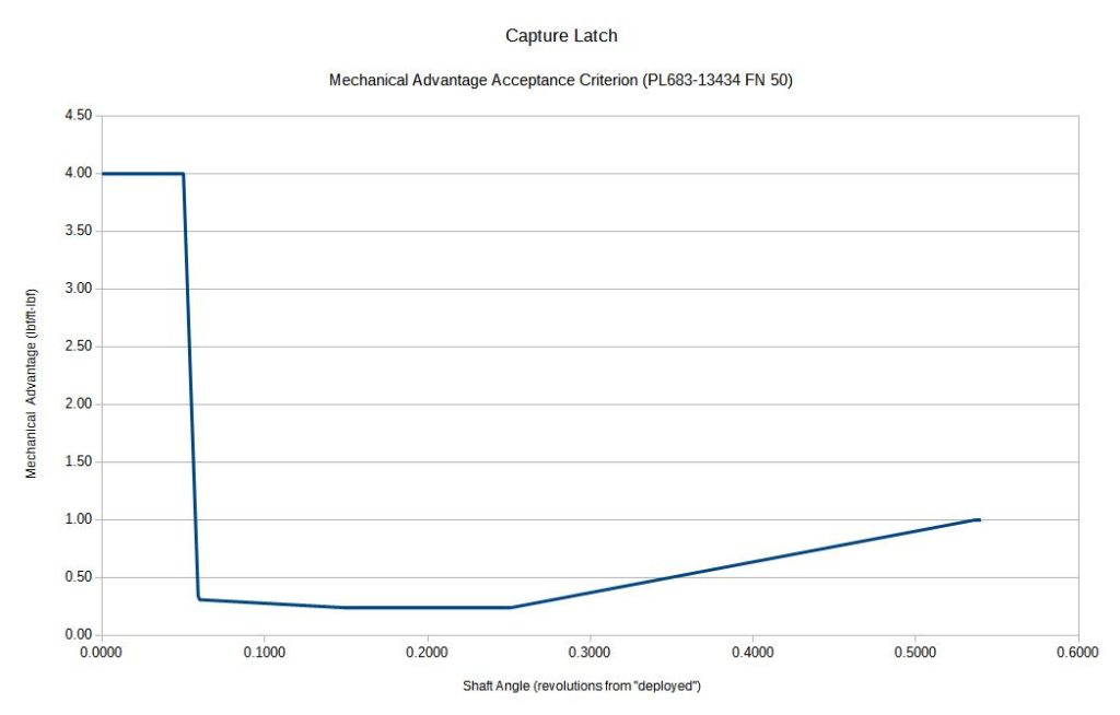
Depending on the latch configuration69 during the closure stroke, the latch can obtain mechanical advantages70 greater than 4, as seen in Figure 35. During the last part of the stroke, the trajectory always converges to the same path71 and, therefore, to a consistent mechanical advantage. The advantage in the early part of the stroke can vary widely, because the latch configuration is strongly dependent on the specific location and orientation of the PCBM within the capture envelopes of the four ACBM latches.
Torque limits on the actuator were set to overcome a failed “brakes-on” SRMS based on the calculated mechanical advantage of the latch, without generating self-induced damage of CBM components. In this context, “overcome” means that the latch must provide sufficient force, in excess of contact forces between the two halves, to either slip the SRMS brakes or bend the SRMS arm booms, or (more realistically) some combination of the two. The stiffnesses and slip loads of the SRMS72 were entirely dependent on the combination of joint angles it obtained for each unique berth. See also the related discussion in the summary of CBM qualification requirements.
The potential for “self-induced damage” resulting from “contact forces between the two halves” when the RMS brakes are not on was the genesis of material selection for the contact surfaces on Alignment Guides, Alignment Pins, and Alignment Sockets. The total “come hither” generated by the ACBM, which can peak around 6400 lbf, was demonstrated to be greater than early Alignment Guide designs could tolerate under certain trajectories during the berthing process. Tailoring of the forces generated to the contact stress capability of those items was a significant point of integration in the CBM design. Similarly, the closure forces were a primary lower-bound criterion for the preload of the Thermal Standoffs.
Ready-to-Latch Indicator (RTL)
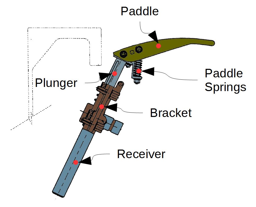
The RTL, shown in Figure 3673, is a spring-loaded plunger with a folding, independently-spring-loaded head. Actuated by the approach of a PCBM Alignment Guide during RMS operations, it trips a contact switch as it plunges. In effect, the paddle of the RTL very conservatively “maps” the sweep of the capture latch onto the tip of the actuating alignment guide. Each “ready” is specifically associated with the latch closest to it. It is possible for the PCBM to be within the capture envelope of the associated latch without getting a “ready” indication, but it is not possible to get an indication without being in reach of the latch.
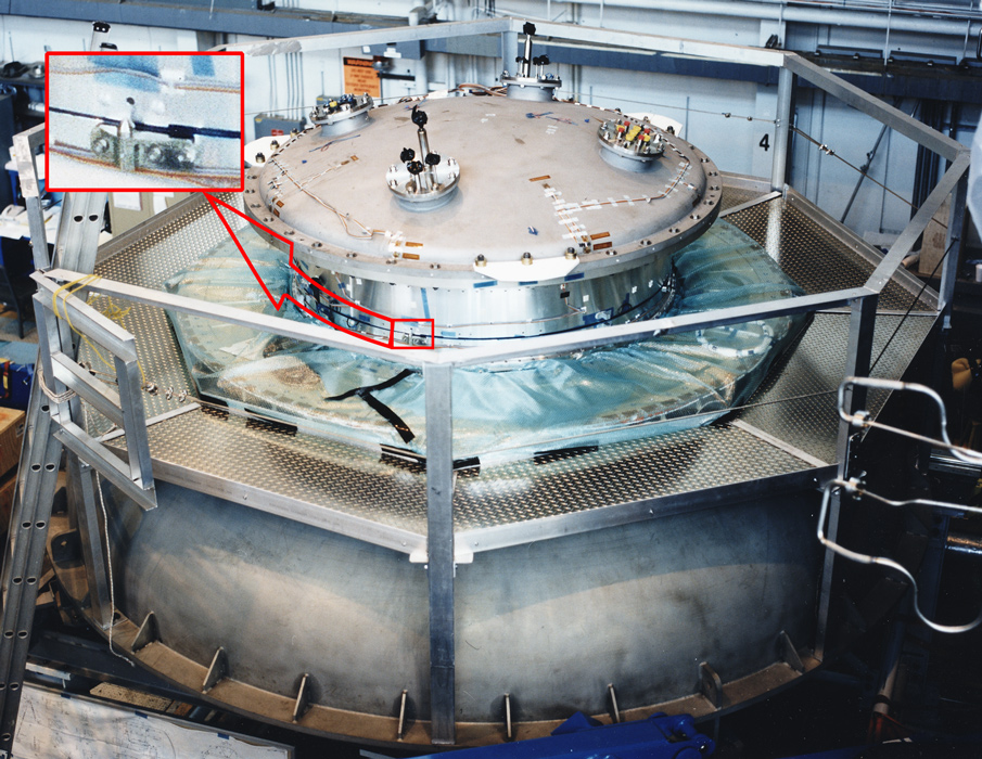
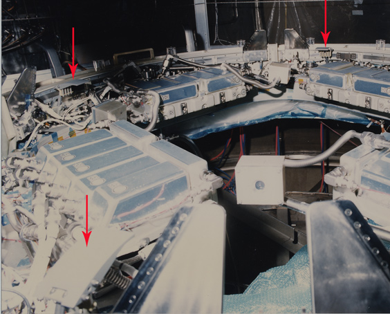
Two of the four RTL’s on the JEM radial port are shown in Figure 37. They’re more visually accessible, however, in Figure 38, which was taken during Assembly Level Qualification Testing. The ALQT photo shows the original, taller version of the RTL74.
Figures 39 through 41 qualitatively illustrate the relative arrangement of the PCBM’s actuating Alignment Guide to the ACBM’s RTL at the three critical points of its function. The RTL folds up under the Alignment Guide, and can be removed once the vestibule has been pressurized.
Actuators and Controller Panels
Physically, the actuation and control elements of the ACBM can be decomposed into 20 actuators, controlled in sets of five by panels of electronics. Each Controller Panel Assembly (CPA) includes one latch controller, four bolt controllers, power conditioning, and signal I/O, so each CPA controls one quadrant of the ACBM. A CPA is shown in Figure 42 along with examples of the associated actuators75. Each CPA excites and receives discrete switch states from one RTL and one Capture Latch, and performs excitation and Analog-to-Digital signal conversion for four Powered Bolt load cells76.
As noted in the figure, two kinds of data busses are employed. An RS-485 bus connects the CPAs within a single ACBM. A MIL-STD-1553 bus, incorporated into the Latch channel77, connects the CPA to upper-tier executive functions in the station.
120 VDC power is supplied to each CPA from the ISS power subsystem. Each control channel within a CPA is electrically connected to its respective three-phase, 10-pole, pulse-width-modulated dc-brushless motor78. The Latch controller serves as a “master” controller for the CBM. Any one of the four CPA’s can be designated by the operator to serve as the master for any specific operation.
All actuators are of a common winding and transmission design, differentiated only by their attachment to their driven mechanism and the connection of cables. The 1242:1 actuator gearbox can provide up to 1600 in-lbf at the output shaft at a speed of 0.5 rpm for up to two minutes for the bolt application78. It can, however, be restricted by the operator to lesser torque values for specific operations. The latch application of torque is “scheduled” with respect to position, and can be further “biased” in order to limit the applied load. All 20 channels of control were derived from the same pump fan controller in an attempt to avoid development costs, and have a speed-control loop at the lowest-level of their firmware control algorithm.
Each actuator is controllable independently of all others:
-Bolt channels are controlled by direction, turn count, and indicated preload. They have several different combinations used for different situations during the berth and deberth processes, all of which report torque79 for diagnostic purposes.
– Latch actuators are controlled by direction, torque, and position. Torque limits are imposed as a function of position and direction of travel, to accommodate the variable advantage of the latch mechanism. The latch actuator is allowed to “stall” for at a user-selected torque for a user-selected period of time80. Stalling allows the latches to reach different positions at any given time, improving the uniformity of loads applied during berthing operations.
In effect, the latch actuator is used as a “servo”, while the bolt actuator is used as a “torquer”.
During operation, the CPA generates as much as 324 W of waste heat for as long as seven minutes78. Dissipation of heat was a significant integration issue, being a subject of both thermal balance and contact resistance testing during CBM development. A thermal gasket lies between each CPA and the hatch beam to which it is bolted, while the CPA’s themselves are surfaced with a tape having carefully selected thermal-optical properties. The low-level speed control loop was also a significant point of integration within the CBM, being able to surge the contact load more quickly than analytical methods and computers of the day could readily predict.
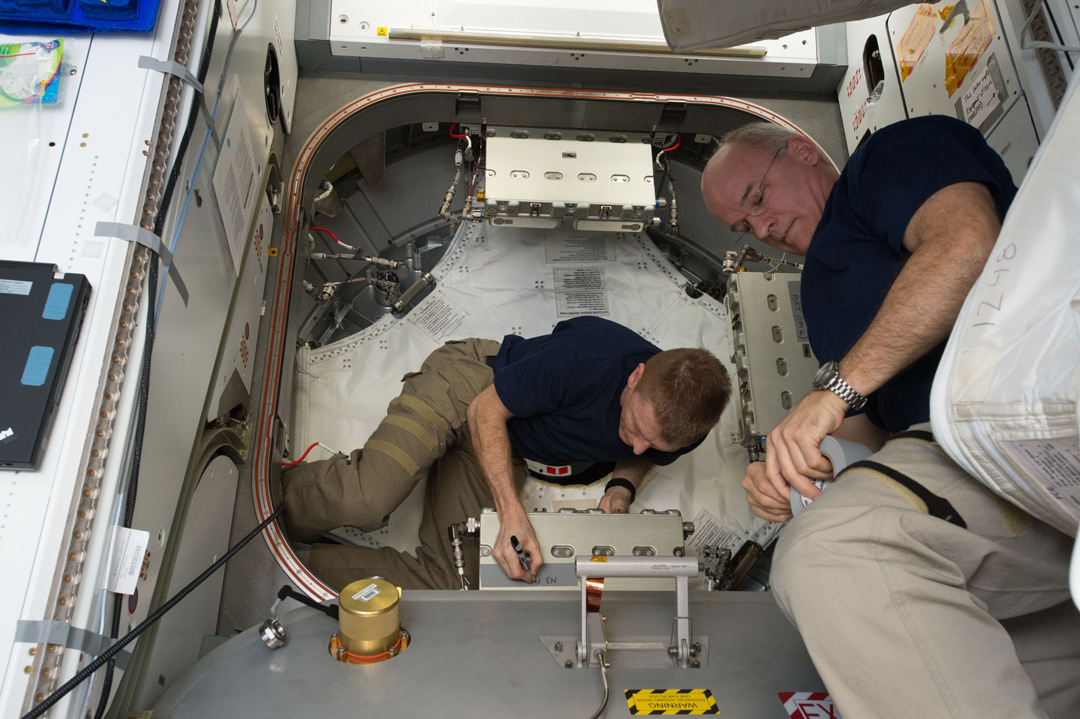
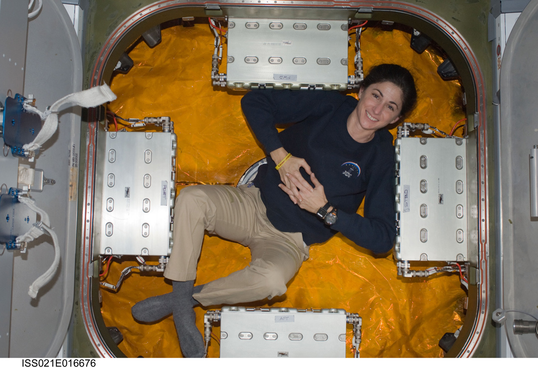
Because the CPAs overlap the required 50″ clear passageway of between the hatches at each port, they must be removed after each berthing operation is complete. Removal is by manual means, as shown in Figure 43. However, appropriately-size astronauts may find uses for the vestibule even when the panels are in place (see Figure 44).
- Yes, “sub-mechanism” is an awkward term…but there’s a point to be made: each was a mechanism in it’s own right, as well as being part of the overall mechanism. In a sense, the semantic error was in calling CBM a “mechanism”, instead of a “machine”. Spilled milk under the bridge…[↩]
- And, perhaps, of the ontologically obsessive author[↩]
- But not a secondary purpose.[↩]
- By which accounting, there would be 85 distinct mechanisms, 84 of which next-assemble into the 85th. [↩]
- Although NASA historically performed customer-discretionary CBM/CBM “fit checks” at the Element level whenever possible during pre-flight operations.[↩]
- Not all ACBM’s are interchangeable with respect to their locations on Pressurized Elements.[↩]
- “Provides for” does not, however, mean that there are seal beads on both sides. One side provides the land against which the beads are compressed.[↩]
- The -2 and -3 were substitutable parts for assembly-level qualification[↩]
- Includes actuator[↩]
- treated as being part of the Powered Bolt for mechanism count(40 or 44)[↩]
- Sometimes referred to as the “tee flange”. The flange on the CBM ring that bolts to the tee flange is sometimes referred to as the “inboard flange”.[↩]
- .2500-28 UNJF 3A A286 CRES or MP35N [↩]
- e.g., when investigating root causes of pressure loss[↩]
- See the Parker O-ring Handbook[↩]
- Sometimes referred to as a “substrate”.[↩]
- Almost as if an o-ring had been stretched around the segment into the groove.[↩]
- I am not aware of any IVA seal having been used, or any leak test having been executed (let alone failed).[↩]
- Refer to Table 1 for the counterpart relationships across the CBM/CBM interface plane.[↩]
- Formally, 0.625-18UNJF[↩]
- PL683-13450, Flag 13. [↩]
- The term “follower”, when used in the context of mechanisms, generically refers to a part having motion that is not a degree of freedom. The term is used in several different places on CBM. Other terms are sometimes used for this concept, so attention to context is strongly advised.[↩]
- Looking from the head side.[↩]
- Much.[↩]
- If the follower has been “dropped” off the tip of the shaft.[↩]
- The actuator is outlined in Figure 10, but not shown in Figure 12.[↩]
- In operation, either the follower or a PCBM nut[↩]
- Axial (“reach”) of the shaft, and roll about the shaft’s longitudinal axis are controlled on the bolt’s side of the interface[↩]
- This is a local reference frame, distinct from (but related to) the reference frame established by the nominal ACBM/PCBM interface plane.[↩]
- That is, the nut “complies” with the bolt’s orientation.[↩]
- The chamfer is clearly visible in Figure 6[↩]
- In practice, it doesn’t really have uniform distribution, but that’s most general stochastic case.[↩]
- Shear and bending loads are mostly mitigated by the details of the load paths on both sides.[↩]
- Including the seal.[↩]
- The function is variously referred to as “torquing”, “tightening”, and “preloading”.[↩]
- Working from top to bottom.[↩]
- Which are effectively lapped into a matched set[↩]
- The bolt and nut are not, however, match lapped.[↩]
- “Lubrication Handbook for the Space Industry”, available through NTRS.[↩]
- That would only make things worse.[↩]
- As are the first two values for TC1. A good argument could be made that too many units would be built for a mere two standard deviations to suffice.[↩]
- That preload provides zero margin of separation under external load. The margin is actually negative once joint relaxation is considered.[↩]
- “Tighten by torque isn’t going to work for this.”[↩]
- available on NTRS[↩]
- An argument could be made that it wasn’t very important for single-berth locations, but the “common” in “Common Berthing Mechanism” had to be considered.[↩]
- Look again at Figure 3[↩]
- Sometimes referred to, erroneously, as “error”. [↩]
- As actually implemented, tolerance on accuracy was levied only at the two extremes of the range shown. Physics strongly suggests the intermediate performance is linear. [↩]
- e.g., retracting the bolt beyond the maximum required to drop the follower[↩]
- In the case of the socket, that means “below the forward face of the Gask-o-seal substrate”.[↩]
- That is, on the longitudinal and circumferential axes at each radial port ACBM, and analogously on each axial ACBM port.[↩]
- like a screwdriver into a Philips-headed screw[↩]
- As noted above, it is unlikely that any pair of mated rings has experienced such motion after mating is completed. It is also nearly impossible to verify whether they have.[↩]
- Location, geometry, surface finish and material contact stress limits.[↩]
- To less than 0.01″.[↩]
- Actually, two springs in parallel.[↩]
- Basically just a gusseted L-bracket.[↩]
- As opposed to continuous.[↩]
- Sometimes referred to as a “blade”.[↩]
- Angular and linear dimensions are taken from SSP 41004U.[↩]
- around the longitudinal axis of the vestibule[↩]
- The concept of wet lubrication was discarded in order to avoid making a mess during IVA operations in the vestibule.[↩]
- on the “45’s”[↩]
- The EVA time advantage was later lost when the Deployable M/D Covers, which require one-time EVA preparation, were included in the design of Node radial ports. Constraints driving the the 45° azimuth location, however, remained applicable to the covers in their launch condition.[↩]
- The possibility is further mitigated by the accuracy of geometric relationship between the RTL and the sweep of the Capture Latch.[↩]
- Material, geometry, and surface finish[↩]
- That were themselves sized to accommodate a failed “brakes on” SRMS[↩]
- All other figures in this section are ad-hoc, manually positioned cartoons. They’re close, but should not be interpreted as if they’re configuration-controlled quality.[↩]
- “remote”, as in “the end not at the drive shaft”.[↩]
- Combination of internal angles between the linkages[↩]
- lbf of output force for in-lbf of input torque. This ad-hoc definition is an example of a Figure of Merit.[↩]
- Because the Alignment Guides, Pins, and Sockets leave it nowhere else to go.[↩]
- Including the snare on the end.[↩]
- As with the Capture Latch figures, only the photos in this section are “real”. All other figures are “cartoons”, and should not be interpreted as being perfectly “to scale”.[↩]
- The height was reduced to mitigate the potential of entrapment due to constrained motion during the RMS operation.[↩]
- CPAs are also visible in the mid-ground of Figures 27 and 37.[↩]
- McLaughlin, Rickard J. and William H. Warr “The Common Berthing Mechanism (CBM) for International Space Station” (2001-01-2435), © 2001 Society of Automotive Engineers.[↩]
- For which reason the Latch box on the CPA is taller than the Bolt box.[↩]
- McLaughlin and Warr[↩][↩][↩]
- The word “torque” here really means “current”: the actuators have no torque-sensing instrumentation. [↩]
- That is, it will continued to apply torque to hold against reversal of direction.[↩]