Distinguishing requirements
Many of the Qualification Requirement topics that distinguish the ACBM and PCBM from all other components of the International Space Station (ISS) are addressed in both of their specifications 1. The topics held in common are more easily understood when discussed together. Other distinguishing requirements are applicable to one side only, and will be discussed subsequently.
Topics held in common by ACBM and PCBM
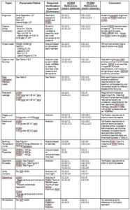
Table 1 summarizes the distinguishing requirement topics held in common by both sides. The table merely summarizes some of these requirements2. The table neither attempts to show all requirements, nor to replicate in their entirety those that are addressed. References in the table are by way of specification paragraph numbers. Paragraph numbers in Section 3 (e.g., “3.2.2.1”) contain the “design-to” requirement. Each aligns with exactly one “verification” requirement in Section 4 of the same document. Comments in the table are either based on the original verbiage of the requirements, or on Section 6 of S683-29902.
Topics unique to ACBM
In addition to topics addressed above, S683-29902B contains some that are unique to the Active side. Those requirements are summarized in Table 7.

Safety topics
Although they are not distinct from requirements allocated to items other than the CBM3, these requirements are crucial to operations. Other than naming which side is being addressed, they are identical for both ACBM and PCBM.
(1) Catastrophic hazards: No combination of 2 failures, 2 operator errors or 1 each in the [CBM] shall result in a disabling or fatal personnel injury, or loss of 1 of the Orbiter, ISS, or major ground facility. (Verification is by non-specific analysis4.)
(2) Critical hazards: No [CBM] single failure or single operator error shall result in a nondisabling personnel injury, severe occupational illness; loss of an ISS on-orbit life sustaining function or emergency system, or damage to the Orbiter or ground facility. (Verification is by non-specific analysis5.)
Requirements for Orbital Parameters and orientation
As noted in the CBM Engineering summaries, the orbital elements and orientation of a spacecraft contribute to predicting the temperatures of its various parts. The only reference to these issues in S683-29902B and S683-28943E is in the context of Meteoroid/Debris protection. No CBM-level requirement is allocated in regard to this material, so it had no enforceable effect on CBM development. In the present context, however, it is useful to note that the developmental altitude for ISS was specified by those “requirements” as 215 nautical miles, with an inclination of 51.6 degrees.
Two spacecraft attitudes6 are specified: “LVLH [Local Vertical, Local Horizontal] 10 percent of the time (Orbiter attached)” and “TEA [Torque Equilibrium Attitude] 90 percent of the time (Orbiter not attached)”. These two “attitudes” actually specify different control strategies:
(1) “LVLH” refers to the frame of reference that “orbits”7. In LVLH, the spacecraft consistently points the same side down.
(2) “TEA” specifies that the spacecraft will orient itself in whatever direction minimizes the total of all torques externallyacting on the spacecraft, thereby minimizing the amount of energy required from the Control Moment Gyros (see, for example, Control moment gyroscope). The TEA attitude was of relatively little interest to most of the CBM development effort, which focused on Orbiter-attached ISS Assembly operations when the Orbiter was attached.
Influences derived from installed locations
The installed locations critically influence the CBM, determining the boundary conditions for deflections induced by internal pressure and the thermal conditions under which the CBM operates. These issues are recognized in the specified requirements by way of references to an Interface Control Documentation (ICD) SSP 41004, as shown in Table 1. The ICD controls how CBM’s mount to Pressurized Elements. Additional influences follow from the capture load requirements, also shown in Table 1.
Some of these issues directly drove features of the design, while others appear directly as requirements. Some of them also drove circumstances for qualification analysis and testing. Several of them required dedicated projects as precursors to formal Qualification activities, discussed at moderate length in T683-13850-3, Section 3.2. Those projects are summarized here, supported by references to useful relevant texts to make them more accessible8. A few simple examples and arithmetic calculations based on (eventual) test and flight operations are also included to aid in visualization.
Geometric envelopes
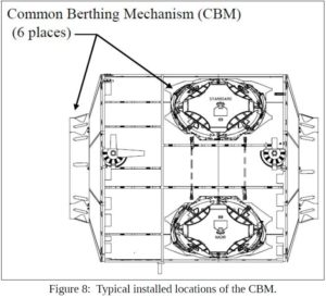
CBM’s can be installed either axially- or radially-oriented on the Pressurized Element, as shown in Figures 8 – 11910. PCBM installations are on axial ports only, while ACBM’s can be installed either axially or radially.
The converse statement makes it easier to understand why: axial installations may be either long (PCBM) as shown in Figure 911 or short (ACBM) as in Figure 10, but radial installations (Figure 11), being constrained by the diameter of the NSTS Payload Bay, can be short only (therefore, Active only). The depth of insertion into the convex hull of the Element’s primary structure, evident for typical radial installations in Figure 11, intuitively demonstrates the qualitative difference.
Pressure-induced deflections
SSP 41004J provides Figure 12 showing the constraints (exaggerated for emphasis) on the maximum pressure-induced radial deflection at the joint where a pre-berth ACBM ring is mounted on a Pressurized Element’s radial port. The angles shown are +/- 11.25 degrees, which is half of the span between any pair of Powered Bolts. In addition to radial deflections, the interface may tangentially displace by as much as 0.040 inch, and may displace out of plane by up to 0.008 inch within any 7.5 degree arc. The ring can also rotate from -0.8 to +0.63 degrees around the local tangent within the constraints shown in Figure 13 (which is also exaggerated for emphasis).
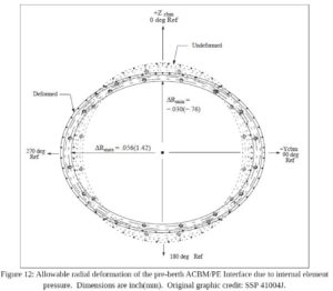
Constraints on the pressure-induced deformations of the pre-berth PCBM ring are similar: radially to 0.39 inch, axially to 0.024 inch, out of plane to 0.005 inch within any 7.5 degree arc, with rotation about any local tangent being limited to between -0.060 and 0.375 degrees. For both rings, the deflections quoted here result from detailed stress analysis, which was in turn validated by Element-level test on the Node Structural Test Article (STA)12.
The deflections discussed above arise from pressure differential across the bulkhead to which each CBM ring is bolted13. Once the two halves are mated and pressure is introduced into the vestibule, most of the distorting forces are relieved.
During vestibule pressurization and concomitant relief of distorting forces, the rings can dynamically change shape. The faying surfaces at the CBM/CBM interface plane can move relative to each other during the event, scrubbing the CBM/CBM seal in a radial direction while it is under compressive load. This is the worst possible circumstance for scrubbing a face seal14. Verification of performance during and after exposure to these circumstances is clearly stated in the requirements, above15.
Thermal circumstances
As with the structural distortions discussed above, the thermal characteristics of interest here are those strongly influenced by factors outside the direct scope of the CBM development effort. They fall into two broad categories: 1) the gross thermal mass of the elements to which CBM’s are attached and 2) the spacecraft’s flight conditions.
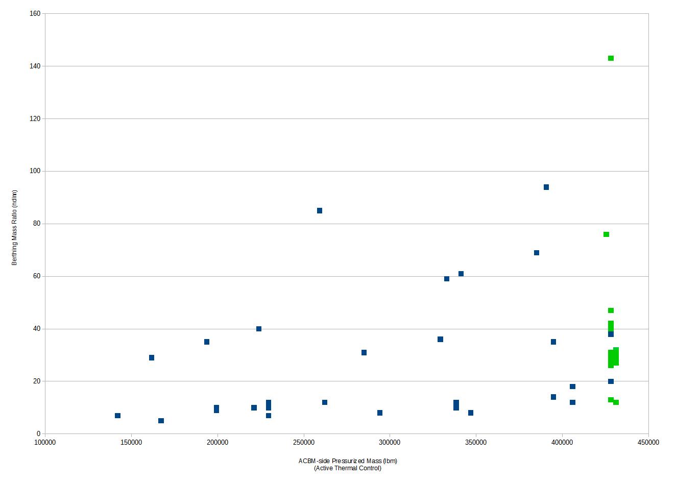
Under any given set of thermally-relevant circumstances, physics stipulates that a larger thermal mass changes temperature more slowly than a smaller one. Figure 14, which is based on the data compiled here, shows the distribution of mass ratio between two Pressurized Element clusters (Active side÷Passive side) for a selection of early berthing operations on orbit 16.
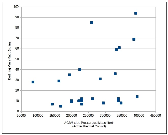
In the first-principles context17 supplied by Gilmore and similar texts, Figure 14 implies that the limit temperatures of the ACBM are relatively dominated by the large mass to which it is attached. Temperature extremes are mitigated, and analyzing the ACBM as if its base is a fixed temperature might be reasonable most (possibly all) of the time. The limit temperatures of the PCBM, on the other hand, might be more strongly influenced by its thermal-optical properties and conductances, and the temperatures might be more extreme than for the ACBM. Analyzing the PCBM with a “fixed” base temperature might not be realistic.
Those observations are worth restating in simpler terms: all else being equal, temperatures of the ACBM are dominated by how much total heat energy there is to lose, while temperatures of the PCBM are dominated by how fast the heat energy can get away.
Figure 14 is produced from data as if looking forward in the early 1990’s 18. It can be expanded to include berths that were not foreseeable in the developmental timeframe, looking backwards from operational status reports. Figure 15 shows that the “unforeseen” berths, shown in green, add only a single outlier to the original body of data19.
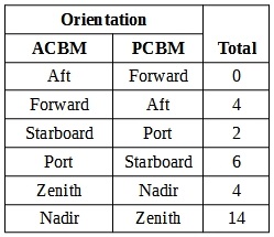
The same sources referred to above also provide information about the spacecraft orientation during berthing events. Again as observed in Gilmore, this spacecraft-level characteristic is an important determinant for temperatures on both sides of the interface plane. From first principles, the coldest temperatures are generally expected on things that point zenith-ward, and the most moderate temperature ranges on things that point to nadir. Table 8, which is based on the same sources as Figure 14, summarizes the orientations during the early (“foreseen”) events on orbit.
Things that point to the sun are the warmest, but that evaluation requires analysis in the context of how the orbit’s line of nodes precesses. As noted in the requirements discussion above, the orbital altitude (215 nm) and inclination (56 degrees) were also necessary in order to conduct that analysis, even though they were not formally specified.
These relationships are somewhat abstract, but easily shown from simple first principles. Their robustness with respect to changes in the spacecraft-level assembly sequence is inherent in the conceptual design, which always places the ACBM on orbit first, berthing sometimes-small Elements (e.g., Cupola) to Element clusters of increasing size over time. They remained pertinent from the Space Station Freedom program (where Elements could be up to 44’ in length20), through the Space Station Alpha program, to the International Space Station program (where the JAXA “Kibo” Element, for example, is 36.7’ long). The change in length (which reduced the average Element-level launch mass) was due to the change in orbital inclination from 28.5 degrees (Freedom) to 51.6 degrees (ISS), which adversely impacted the payload mass capability of the NSTS. That change did, however, alter some of the detailed temperatures, again due to the change in inclination.
Remote Manipulator System (RMS) configuration
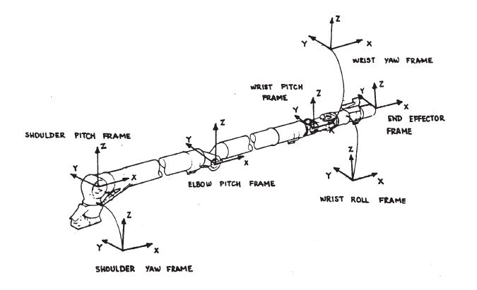
In contrast to the thermal circumstances described above, loads and trajectories induced by the Shuttle RMS (SRMS) during capture of the chase vehicle are not robust with respect to changes in spacecraft-level configuration. They are strongly sensitive to SRMS joint configuration because of the segment lengths and the particular combination of rotations at each joint. The relevant joint dynamic frames are shown in Figure 1621. Absent bending of the structural segments, motion can occur at each joint around the joint-specific transverse axes only.
While it is difficult to reconstruct mission-specific geometries and load trajectories from publicly available data, insight can be summarized from Appendices E and F of T683-13850-3. The appendices report a 65-case d-optimal22 analytical survey executed to discover maximum contact loads.
Appendix E continues by reporting the synthesis of non-flight berthing cases to excite the desired contact-load behavior. The specific cases analyzed and tested for qualification are not, therefore, directly traceable to any specific on-orbit operation. In effect, the approach suggests that the combined test and analysis approach decoupled many aspects of capture from any particular program-level considerations (e.g., spacecraft-level configuration).
Appendix F demonstrates the wide variety of resulting trajectories. None monotonically close the gap between the ACBM and PCBM during capture, further substantiating the notion that the loads and trajectories during capture are not robust with respect to changes in SRMS joint configuration.
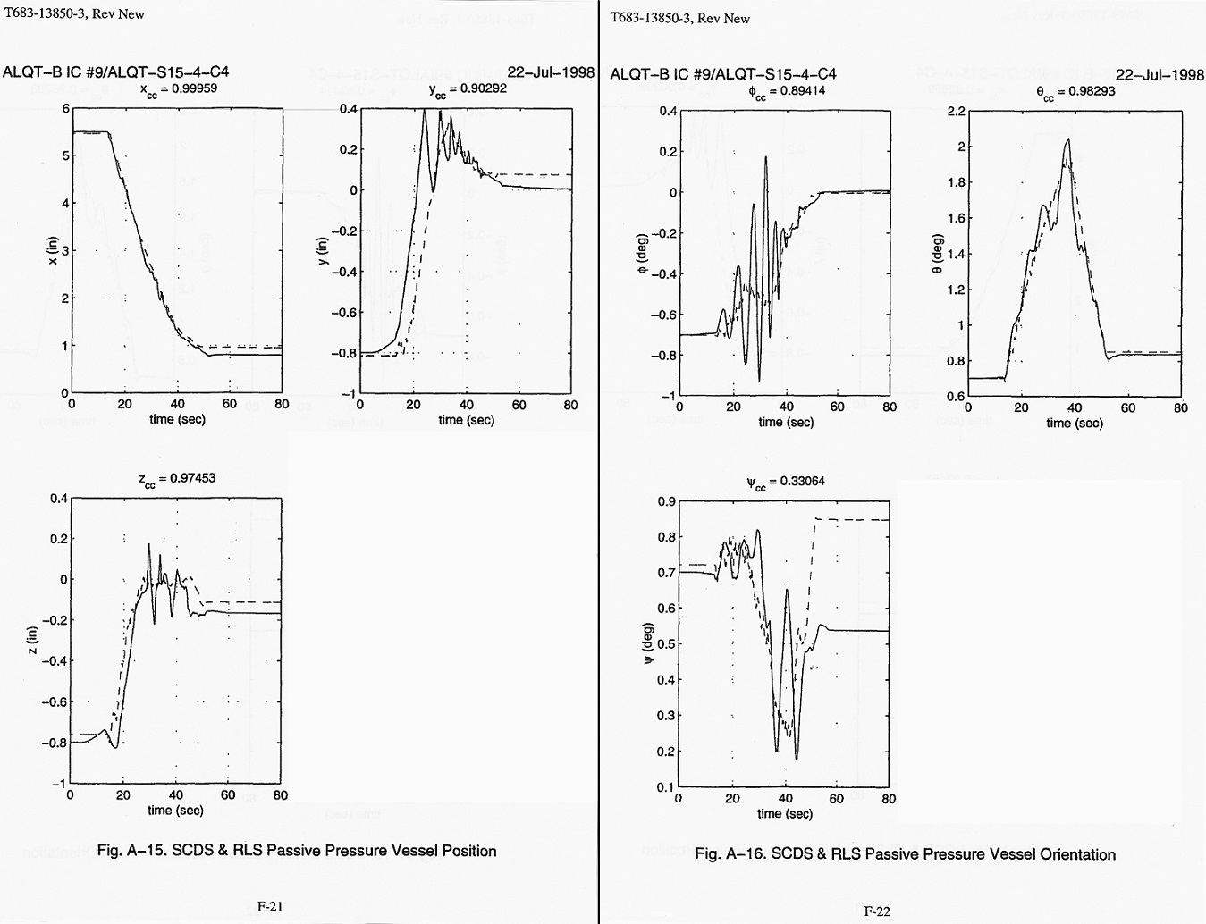
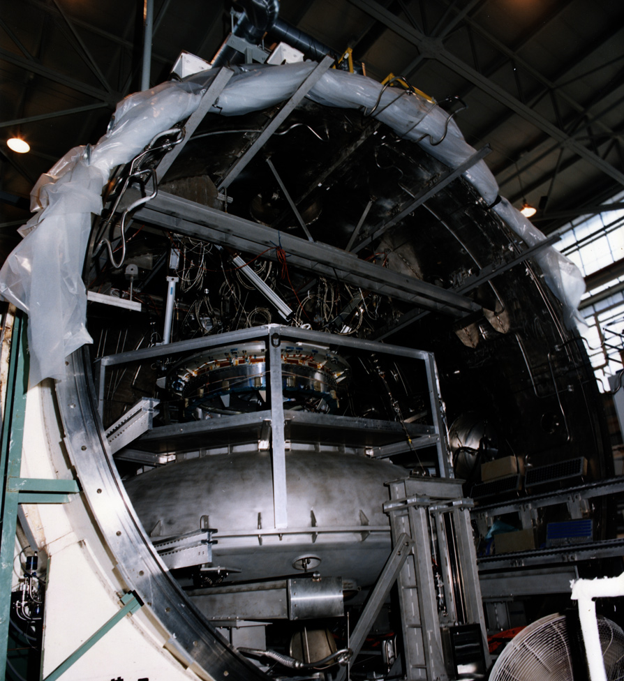
Figure 17 shows a typical example of the PCBM trajectory during simulated capture, taken from Appendix F. Temporary divergence of the trajectory, eventually followed by convergence, demonstrates the basic situation described above. In the figure, “RLS” refers to leg position sensors on the fixture holding the PCBM, which was a Stewart Platform suspended from the top of the 20-foot diameter vacuum chamber in which the test was conducted (see Figure 18). “SCDS” refers to the analytical model of that fixture.
In the context of the reported analytical survey and the reported results of subsequent analysis, the genesis of the sole operation mentioned in the specifications (see Table 2) remains unclear from the publicly available documentation. More succinctly: it is evident from the results that SRMS joint configuration is important, but the available documentation does not make clear the technical rationale for how it was dealt with in the formally specified requirements.
- S683-29902 and S683-28943, respectively[↩]
- Sometimes referred to as “identifying requirements”, these are the combinations of topics, parameters, values, and circumstances that characteristically make the CBM unique from all other items in the same project. Many other requirements exist, and some of them might be very important, but most are equally allocable to CI‘s other than the CBM.[↩]
- That is, they are not “distinguishing”.[↩]
- S683-29902B & S683-28943E, 3.3.6.1.1, as verified by 4.3.3.6.1.1. A few more specific requirements for the ACBM also exist.[↩]
- S683-29902B & S683-28943E, 3.3.6.1.2, as verified by 4.3.3.6.1.2. A few more specific requirements for the ACBM also exist.[↩]
- The tabulated requirement miss-spells it as “Altitude” in both specifications, but the intent is clear from the context.[↩]
- See Wertz op. cit., Ch. 2, which refers to this concept as simply “local horizontal” or “local tangent” coordinates.[↩]
- Section 3.2 having been written for “insiders”.[↩]
- Original graphic credit for Figure 8: Underwood, Steve, et al. “Implementation of Leak Test Methods form the International Space Station (ISS) Elements, Systems and Components”, The Boeing Company, Huntsville, AL (2007). Retrieved from NTRS.[↩]
- Original graphic credit for Figures 9 – 11: SSP 41004J.[↩]
- Figure 9, 10, and 11, original graphic credit: NASA, SSP 41004J.[↩]
- T683-13850-3, section 3.2 quotes the Node STA reports as T683-85281-1 and T683-85283-1 for Proof Pressure and Static Flight Loads, respectively.[↩]
- PCBM deflections are, of course, not applicable to installations without a bulkhead.[↩]
- See the Parker O-ring Handbook.[↩]
- …leading to subsequent accusations of leak test perversion.[↩]
- A Mass Ratio of 1 represents a berth where the total mass of Pressurized Elements on the ACBM side is the same as on the PCBM side.[↩]
- That is, without additional reference to the details of CBM design.[↩]
- Hopson, George D., et al, “Space Station Freedom Pressurized Element Interior Design Process”, MSFC (1990).[↩]
- This is the BEAM, which wasn’t a glimmer in anybody’s eye during the original development of the CBM.[↩]
- Hopson, et al, op.cit,.[↩]
- S683-29902B, op. cit., Appendix A. [↩]
- See also Atkinson, A.C. and A.N. Donev, “Optimum Experimental Designs”, Clarendon Press, Oxford (1992), Chapter 11.[↩]