My Standard Caution About Examples applies to this page.
Start with an excerpt from a general specification for retention and release devices as they’re used on deployable spacecraft mechanisms1:
“Devices that may be subject to binding due to misalignment, adverse tolerances, or contamination shall not be used.”
Background
The topic here is “binding”: the dynamic condition where a mechanism fails to actuate smoothly. “Binding” can mean that the mechanism’s actuation stutters. It can also mean that motion stops altogether. Binding is a particular mode of failure for the “release” function which, as written in the example, is directly allocable to the retention device itself, possibly being distinct from the deployable mechanism’s “Deploy” function.
For the purpose of this exercise, “binding” is taken to mean thatthe application of more force does not clear the issue, but may very well make it worse – up to and including permanent damage to the retention device itself. This notion allows it to be distinct from the case where the device (or its installation) is simply stiffer than expected, both of which are dealt with elsewhere in MIL-A-83577B2.
Requirements Issue
The issue of binding can be difficult to address as either a requirement or a feature without accidentally creating an unreasonable constraint on the retention device. It is not unusual to see the non-cognoscenti try to over-simplify it as “without stopping”, but that ignores the slip-stick reality of how mechanisms transition between motion and non-motion.
The specific issue at hand is conversion of the qualitative “binding” topic into a quantitative (parameterized) concept for the purpose of objective verification3. The alternative to conversion during the requirements phase is to haggle over the intent during verification closeout. Being subjective, that haggling is subject to significant biases of many types. It occurs too late in the program for recovery from any adverse effect of the argument4.
Discussion
Requirements are usually more economically stated in a positive sense by defining the characteristic that’s desired rather than one to be avoided. This is because Western logic generally considers proving the negative to be much more difficult (and expensive) than proving the positive. If nothing else, it avoids the problem of distinguishing between evidence of absence and the absence of evidence: we can more easily argue about the implications of evidence that is than we can argue about the implications of evidence that isn’t.
A Smooth Trajectory
The qualitative opposite of “binding” is a “smooth” trajectory. A notional example is shown by the curve of Figure 1. The specific shape is not relevant to the exercise at hand. This particular curve is generated as a sigmoid function, for which the value5 of k simultaneously tailors the slope and curvature. The curve has been shifted and normalized to start at position == 0 at time == 0, completing at position == 1 at time == 1.
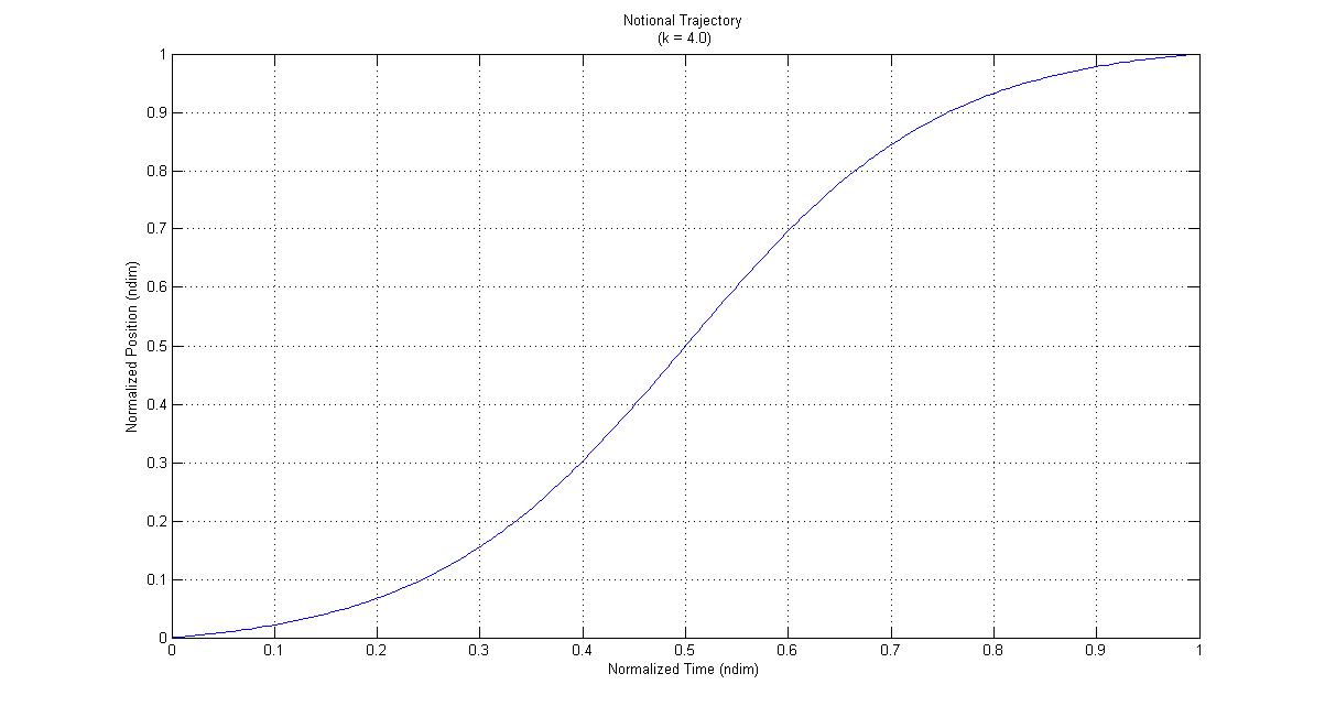
We know with certainty that the trajectory of Figure 1 is “smooth” because the equation that generated it is continuous and infinitely differentiable in its independent variable. In real mechanisms, this is not necessarily true. That reality has to be accommodated by the methodology for defining a FoM, which is why some form of differencing is usually included.
Unsmoothing the Trajectory
Figure 2 randomly shows the trajectory as perturbed to make it very “unsmooth”, as if obtained from a real-world test article. It will be noted that the perturbed trajectory stops and starts, as if the mechanism repeatedly bound during actuation. The reader should be able to intuitively discern the choppiness of the perturbed trajectory in comparison to the original.
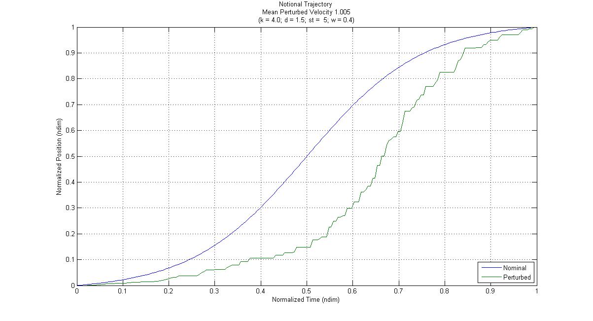
The perturbation in Figure 2 was generated by an algorithm operating directly on the trajectory, having no particular relationship to physics. Technically, this would be referred to as a “behavioral model” rather than a “causal model”. Its use is acceptable here only because we’re describing the method for converting a qualitative requirement into a quantitative one.
Comparison of the Smooth and Unsmooth Trajectories
There are many ways to compare the two curves without making reference to the (non-causal) random variables that perturbed the original6. Most of them involve some form of filtering and some form of differencing. These two types of operation might be performed in either order, depending on the details of the method.
Since the purpose here is to expose the concept of converting a qualitative topic into a quantitative one, a simple approach is selected: Power Spectral Densities (PSD) for the two curves will be differenced, and associated Figures of Merit (FoM) will be heuristically defined7.
Aside: Addressing Cognitive Bias
Heuristics always bear significant potential for cognitive bias. In a contracted (or regulated) development environment, that would be mitigated through peer review of the FoM, where the peers have significant experience in the specific technical domain (in this case, deployable mechanisms for spacecraft). The System Engineer’s role would be to moderate the process (because the SME‘s will want to argue amongst themselves and execute extensive Science Projects) that defines the FoM and to ensure the objectivity of the resulting measures and algorithms.
The objective of the exercise at hand does not hinge on the removal of bias, so the mitigation process has not been executed. This exercise is merely a demonstration of the conversion concept itself, and recommends no particular measures.
Aside2: The Criticality of Technical Domain
The importance of having SME’s of the correct technical specialization cannot be over-stated. In the present example, having a vanilla-flavored mechanism engineer would not be sufficient, because the space environment requires unique considerations. Similarly, having a spacecraft structural engineer would not suffice, because the dynamic nature of mechanisms makes them quite distinct from mere structural aspects.
This implies that a journeyman (non-specializing) System Engineer must invest some time, perhaps significant, into research with each new assignment. It is not necessary to become a SME, but it is necessary to speak their languages. As a practicing System Engineer, it was not unusual for me to spend two or three months on this issue with each new assignment8. Some organizations eliminate it by requiring their System Engineers to narrowly specialize so that they’ll correctly identify the SME’s they need for each new project.
Figure 3 estimates and compares the PSD for both versions of the trajectory shown in Figure 2. A more generally applicable FoM is more portable9.
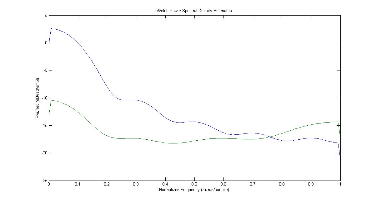
Because general applicability is a desirable feature (if not always attainable), the two PSD’s will be differenced. In effect, this suggests that a stuttering behavior can be identified in the perturbed PSD by removing (filtering) the PSD of the intended design. In the design of mechanisms, that intent is often the kinematic stroke10.
This difference is an obvious component to a FoM: if identical to the nominal trajectory (zero difference), the perturbed curve is as smooth as the kinematic. A large positive difference implies a trajectory that has more amplitude in some particular frequency range. Since smaller differences indicate a better match to the nominal stroke, the FoM will accumulate their absolute value across frequency in a direct dependency11.
Note that mere accumulation is not the same as integration, so this example FoM is significantly more simplistic than it might have been. It is also sensitive to the sampling density. Both of these observations will be ignored for the present objective.
It will also be noted that the two PSD’s in Figure 3 cross just above a normalize frequency of 0.75π radians/sample. For the purposes of this exercise 12, that cross-over will be used to identify a frequency above which stuttering is of no concern (“xvr”)13. A higher cross-over frequency is better than a lower one, because it implies that non-kinematic perturbations had less effect on the intentional motion14, so the FoM will be inversely proportional to this factor.
High frequency content being of little concern in this context, the FoM will mitigate its penalization by stopping the accumulation of differences at the cross-over frequency. The resulting Figure of Merit is
As previously noted, this particular FoM is derived for the purpose of exposition, not for formal use. I keep bringing this up because, while I need an example complicated enough to demonstrate all the pertinent features of the approach, I want the reader to concentrate on the basic methodology rather than get wrapped around some specific technical axle.
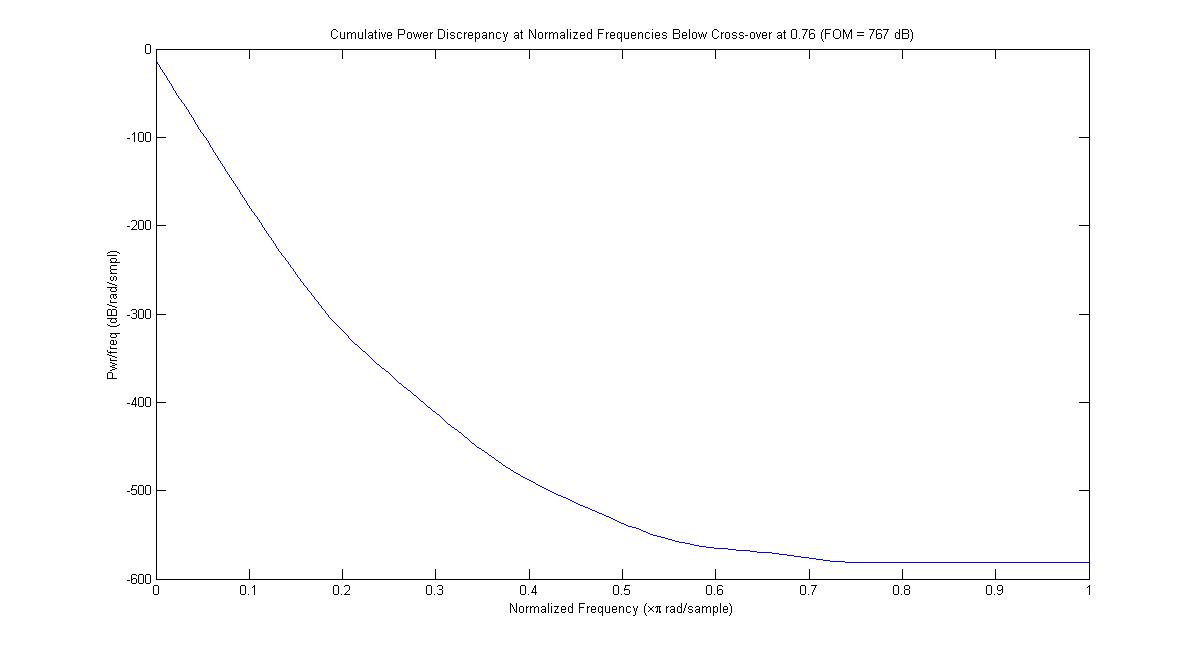
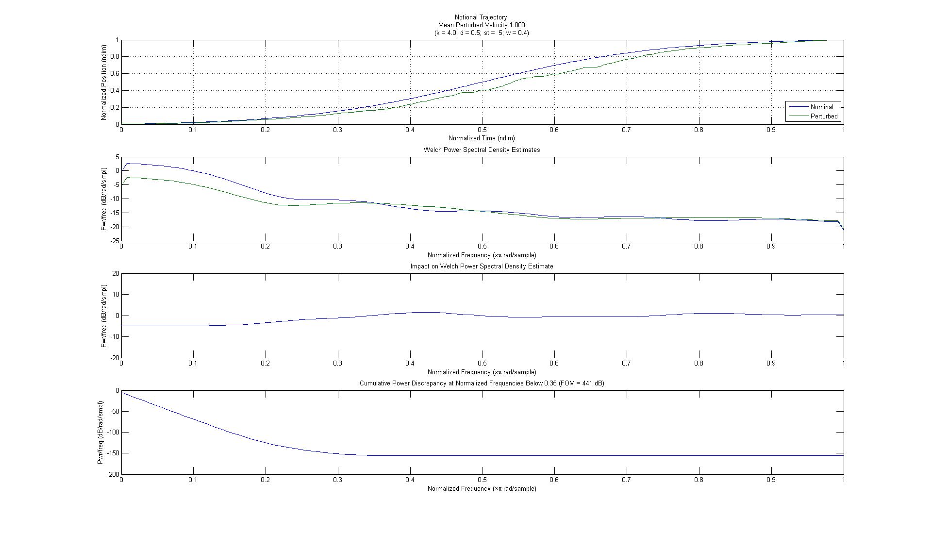
Figure 5 shows the accumulated difference in power through the cross-over frequency visible on Figure 4, with cross-over frequency and the FoM’s value (767 dB) shown in the title.
Although simplistic for real-world application, even this FoM definition is too cumbersome for complete description in a usable requirement text15. Algorithms for complicated figures of merit should always be published under Configuration Control separate from development specifications. The technical content would be similar to the m-file used to generate the figures for this page. Only the name and value of the FoM should be published as a requirement, with explicit reference to the released algorithm.
We can heuristically develop a criterion value by experimenting a little bit with the FoM in order to identify a value that “looks about right”. Figures 6 – 8, each of which incorporates all four plot formats from Figures 2 – 4, gradually reduce the target value to 200 dB/sample for the same algorithmic inputs by running crude Monte Carlo analyses, generally showing the slow improvement in smoothness with reduced values of the FoM16.
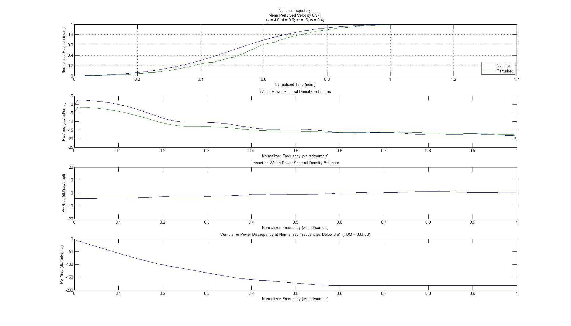
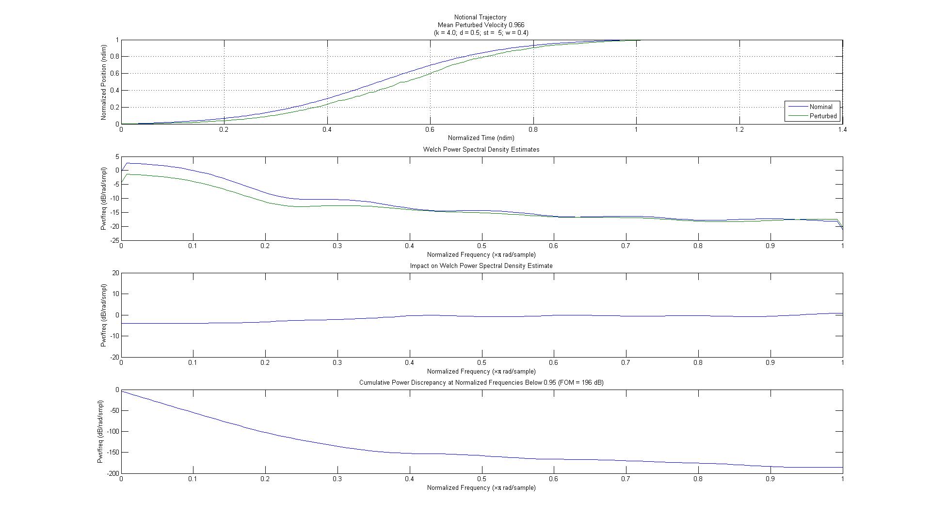
This experimentation, and the numerical value that results from it, is what moves the subjective haggling from the back end of the project to the front end. In effect, it obtains prior concurrence from the contractual (or regulatory) customer: “if we do it like this, we’re done”. Moving that negotiation to the front of the project allows us to make better estimates of projected cost and schedule, with a higher probability of meeting them.
A Quantitative Requirement
The converted, objectively parameterized requirement might look something like this:
“Release and retention mechanisms shall actuate smoothly with respect to their kinematic trajectory within 200 dB/sample, as defined in 55-10042 “Mechanism Trajectory Smoothness Figure of Merit”17 .
The topic is “smooth actuation”, parameterized by the scalar “FoM, per 55-10042”. If the referenced document were project-specific, traceability would be maintained therein and reflected in any supporting requirements database. If not, it could be maintained as a standard practice, and traceability to the original requirement would be established in the supporting database.
Complementation
Being a mere “identification requirement”, the candidate requirement (above) doesn’t meet the general criteria for technical requirements. The verification aspects remain yet to be considered. In this particular case, the derivation of the proposed requirement leads directly to verification by test. The definition of the FoM would require detailed analysis of the design under limit dynamic loading conditions to determine the acceptable combination(s) of the smoothness parameters defined above.
Those loads cannot be available until after the design is substantially complete. The verification requirement cannot (therefore) be “concrete” in the success criteria: it can only specify the methodology by which they have to be derived. As with the FoM itself, that methodology can either be explicit in the verification requirement, or be placed in the same standard practice used to define the FoM18. In the latter case, the verification requirement would look something like this:
“Smooth actuation of release and retention mechanisms shall be verified in accordance with 55-10042 “Mechanism Trajectory Smoothness Figure of Merit”.
Footnotes- MIL-A-83577B, 3.2.2.2.1 [↩]
- In the form of actuation margin.[↩]
- So the original author’s list of root causes is set aside.[↩]
- Good System Engineering practices will always attempt to get any subjective haggling out of the way early.[↩]
- definition (1).[↩]
- Noted in the title of Figure 2 as k, d, st, and w.[↩]
- In practice, I would at least investigate the applicability of both Windowed Fourier and Wavelet analysis to this problem. Both methods typically do a better job detecting discrete events than does the PSD. But the more detailed explanations required in their support would not contribute to the primary objective of this exercise.[↩]
- Some managers tolerated that better than others.[↩]
- Portability (“standardization”) supports collective training among the Engineering Staff which, in turn, supports future cost avoidance.[↩]
- A nominally dimensioned article having theoretical actuation and no load-induced deflection.[↩]
- That is, in the numerator of the FoM’s defining equation.[↩]
- Demonstrating conversion of qualitative requirements.[↩]
- In practice, other criteria such as data acquisition rate might well be applied, but this will suffice for the current purpose.[↩]
- which usually dominates the lower-frequencies[↩]
- And yes, I did that on purpose.[↩]
- The slow reduction suggests that this crude FoM is not very sensitive, but it will do for expository purposes.[↩]
- Don’t bother looking for it…I made it up on the spot.[↩]
- which I regard as the superior approach[↩]